Difference between revisions of "X-Carve: Example Geometry"
Jump to navigation
Jump to search
(Still a work in progress.) |
|||
| Line 9: | Line 9: | ||
# If you haven't already, create an Easel account by following the steps on [[X-Carve: Easel]] page. | # If you haven't already, create an Easel account by following the steps on [[X-Carve: Easel]] page. | ||
## Make sure to [[X-Carve: Easel#Machine Setup|set up the Spark X-Carve]] in the new account | ## Make sure to [[X-Carve: Easel#Machine Setup|set up the Spark X-Carve]] in the new account | ||
| + | # Go to [https://easel.inventables.com/users/sign_in https://easel.inventables.com/users/sign_in] and sign in | ||
# Start a new project using the green button in the upper right of the [[X-Carve: Easel#Easel Start Screen|Easel Start Screen]] | # Start a new project using the green button in the upper right of the [[X-Carve: Easel#Easel Start Screen|Easel Start Screen]] | ||
# Easel will bring you to the [[X-Carve: Easel#Easel Main Screen|Easel Main Screen]] | # Easel will bring you to the [[X-Carve: Easel#Easel Main Screen|Easel Main Screen]] | ||
| Line 67: | Line 68: | ||
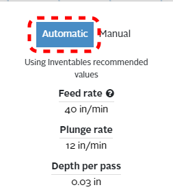
# Ensure that the '''Automatic''' option is highlighted blue by clicking on it. | # Ensure that the '''Automatic''' option is highlighted blue by clicking on it. | ||
#* Feed settings should be similar to the ones shown at left | #* Feed settings should be similar to the ones shown at left | ||
| + | |} | ||
| + | |||
| + | ==Define Project Geometry and Features=== | ||
| + | ''See also: [[X-Carve: Easel - Geometry]], [[X-Carve: Easel - Features]]'' | ||
| + | |||
| + | Each project is built out of a series of [[X-Carve: Easel - Geometry|gometric shapes]], which are used to define the cutting [[X-Carve: Easel - Features|features]]. Easel uses the terms '''Shape''' for geometry, and '''Cut''' for features. Easel allows three types of features: profiles, pockets, and drilled holes. | ||
| + | |||
| + | There are three steps in creating the round tuit, and each step uses a different feature. | ||
| + | |||
| + | ===Outside Circle=== | ||
| + | |||
| + | {| class="wikitable" | ||
| + | |- | ||
| + | ! scope="row" | Step 1: | ||
| + | |[[file:WS_X-Carve_ClassGeometryCircleMarkup.png|center|border]] | ||
| + | | | ||
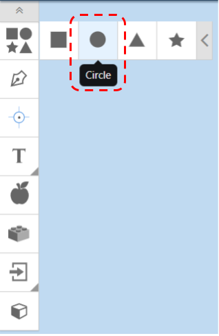
| + | # Start with defining the geometry of the outer shape of the tuit. On the left side of the Easel window, find the Geometry toolbar | ||
| + | #* The tool bar may be hidden. Click the grey box with two chevrons in it, in the upper left corner of the Easel window, to show the toolbar. | ||
| + | # Click the top Shapes box to expand the selection of default shapes | ||
| + | # Choose the Circle option, and Easel will insert a circle in your CAM workspace | ||
| + | |- | ||
| + | ! scope="row" | Step 2: | ||
| + | | [[file:WS_X-Carve_ClassCircleGeometryMarkup.png|center]] | ||
| + | | | ||
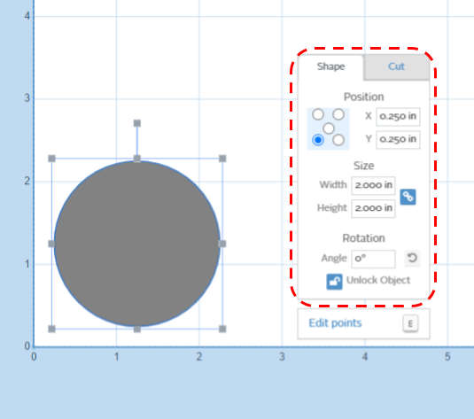
| + | # Once the circle is placed, it can be manipulated using the mouse or using the Shape tab in the pop-up window. | ||
| + | # Use the Shape tab to set the circle: | ||
| + | ## Find the Position control which looks like you rolled a 5 on a die. Click the '''lower left corner''' button | ||
| + | ## Set the X Position to '''0.250 inches''' | ||
| + | ## Set the Y Position to '''0.250 inches''' | ||
| + | ## Set the Width to '''2.000 inches''' | ||
| + | ## Set the Height to '''2.000 inches''' | ||
| + | ## Set the Angle of rotation to '''zero degrees''' | ||
| + | ## Click the '''Lock''' logo at the bottom to lock the circle in position. This will prevent it from being accidently moved as you work on other parts of the project. | ||
| + | |- | ||
| + | ! scope="row" | Step 3: | ||
| + | | [[file:WS X-Carve ClassCircleFeatureMarkup.png|center]] | ||
| + | | | ||
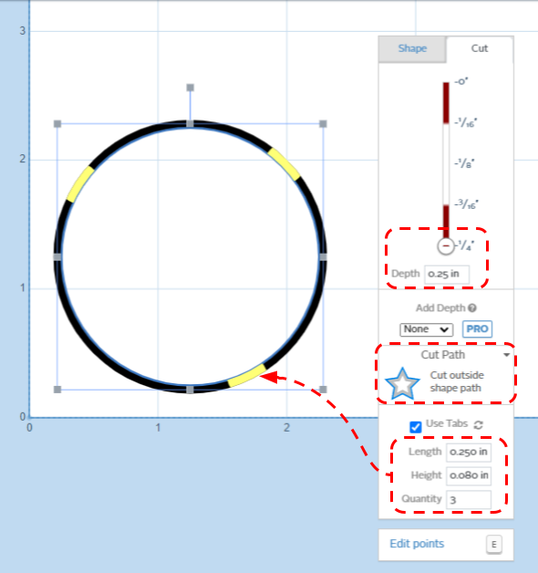
| + | # Now that the Geometry is set, you need to define the feature which will be cut. The default feature is a shallow pocket, as is visible in the simulation portion of the Easel window. Because this is the outside surface of the tuit, you will need to set the feature as a profile cut all the way through the part. | ||
| + | # With the circle geometry selected, click on the Cut tab in the popup window | ||
| + | # Use the Cut tab to set the the profile feature: | ||
| + | ## Set the depth to '''0.250 inches''' | ||
| + | ##* This can be done either by using the slider, or by typing into into the Depth box | ||
| + | ## The Cut Path area currently reads "Cut out a pocket". Click on it, and choose '''Cut outside shape pocket''' | ||
| + | ##* Because Easel now knows you're cutting your project out of the rest of the workpiece, it will automatically add the Use Tabs box to the bottom of the popup window. | ||
| + | ## Ensure the '''Use Tabs''' box is checked (it should be on by default) | ||
| + | ## The default options for tab Length of '''0.250 inches''' and tab Height of '''0.080 inches''' will work fine | ||
| + | ## Set the tab Quantity down to ''3'' | ||
| + | ##* The tabs are visible in the CAM workspace as yellow bars on the black circle. They can be moved with the mouse by clicking and dragging. | ||
| + | ##* Tabs will not be shown in the Simulation portion of the Easel window, though they will be present in the tool paths. | ||
|} | |} | ||
Revision as of 00:33, 12 February 2023
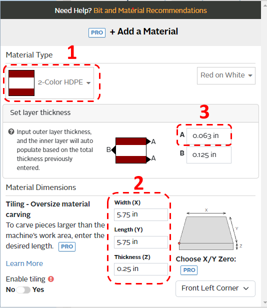
This tutorial will guide a new user through the basic steps of using the X-Carve Router. The project will be a small round tuit out of multi-color HDPE plastic.
Start A New Project
See also: X-Carve: Easel
- If you haven't already, create an Easel account by following the steps on X-Carve: Easel page.
- Make sure to set up the Spark X-Carve in the new account
- Go to https://easel.inventables.com/users/sign_in and sign in
- Start a new project using the green button in the upper right of the Easel Start Screen
- Easel will bring you to the Easel Main Screen
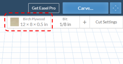
Define Project Material
See also: X-Carve: Easel - Materials
| Step 1: |
| |
|---|---|---|
| Step 2: |
|
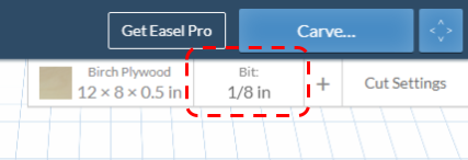
Set Project Cutting Bit
See also: X-Carve: Easel - Cutters
| Step 1: |
| |
|---|---|---|
| Step 2: |
|
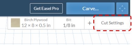
Set Project Feeds and Speed
See also: X-Carve: Easel - Depths and Speeds
| Step 1: |
| |
|---|---|---|
| Step 2: |
|
Define Project Geometry and Features=
See also: X-Carve: Easel - Geometry, X-Carve: Easel - Features
Each project is built out of a series of gometric shapes, which are used to define the cutting features. Easel uses the terms Shape for geometry, and Cut for features. Easel allows three types of features: profiles, pockets, and drilled holes.
There are three steps in creating the round tuit, and each step uses a different feature.
Outside Circle
| Step 1: |
| |
|---|---|---|
| Step 2: |
| |
| Step 3: |
|
