X-Carve: Easel - Depths and Speeds
Introduction
Feeds and speeds is a common machining slang which refers to the feed rate of the cutting tool moving through the workpiece, and speed at which the cutting tool is turning. These two values are some of the most important decisions made in machining, as they influence cutting time, tool life, and surface finish. The Easel software will give an estimated feed rate for cutters, if the cutter is properly defined in the software.
Feed rates are measured in either inches or millimeters per minute (IPM or mm/min). Spindle speeds are measured in revolutions per minute (RPM).
Chip Load
Feed and speed values are calculated based on chip load. Chip load is defined as the thickness of material removed by each cutting edge (flute) while cutting.
Chip loading (CL) can be calculated by using the feed rate (in IPM), the RPM of the spindle, and the number of flutes in the cutting tools using the following equation:
- CL = IPM ÷ (RPM X #Flutes)
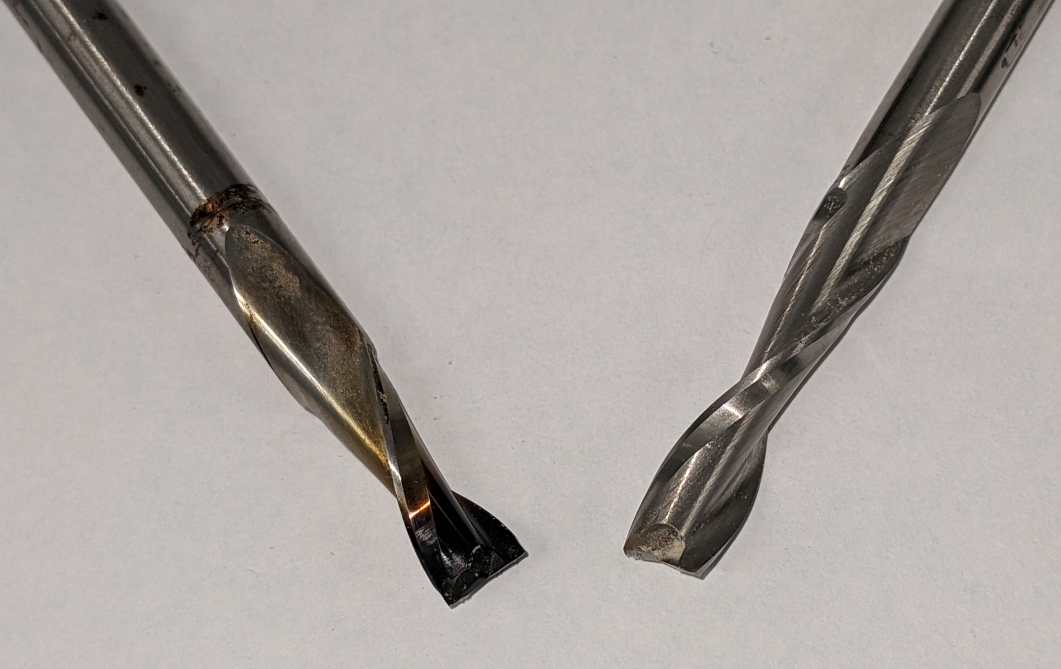
- A chip load which is too low will result in the cutting edge rubbing over the workpiece surface, scraping very fine particles. The rubbing creates a significant amount of heat, which will rapidly dull the cutter and may burn the work surface, while the fine particles create a breathing hazard.
- The image to the right shows two cutting tools, one of which was run with a chip load way below the optimal value. Despite being carbide, the tool has discolored due to the heat and rapidly become dull. In the Spark X-Carve, the most likely cause was high speed settings on the router spindle.
- A chip load which is too high will result in high forces on the cutting edge, which can stress both the cutting tool and the machine. The cutting edge may start to chip, or the cutting tool may snap in half. If the cutter does survive, the surface finish of the resulting part will be appreciably rougher than a properly tuned cut.
- A correct chip load will result in chips or shavings, not dust, and will give good surface finish results while maximizing tool life.
Suggested Chip Load
Ideally, chip load will be determined from the cutting tool manufacturer, as optimal chip load depends on cutter material and geometry. However, if the tool is unknown, the table below can give starting points for chip load. These can be then used to determine feed rate and spindle router speed settings. When using the table, cutters with fewer flutes should use the large end of the given range; cutters with more flutes (up to four) should generally use the smaller end of the range.
| Tool Diameter | ||
|---|---|---|
| Material | 1/8-Inch | 1/4-Inch |
| Hardwood | 0.003 - 0.005 | 0.009 - 0.011 |
| Softwood & Plywood | 0.004 - 0.006 | 0.011 - 0.013 |
| MDF & Particleboard | 0.004 - 0.007 | 0.013 - 0.016 |
| Hard Plastic | 0.002 - 0.004 | 0.006 - 0.009 |
| Soft Plastic | 0.003 - 0.006 | 0.007 - 0.010 |
| Acrylic | 0.003 - 0.005 | 0.008 - 0.010 |
Feed Rate
The feed rate is the sped at which the X-Carve moves in the X-Y plane. This value is measured in either inches per minute (IPM) or millimeters per minute (mm/min). Feed rates are dependent on the calculated chip load and the limits of the machine.
- The Easel software will give an estimated feed rate for many cutting tools, if the cutting tool is properly defined in the software.
- The X-Carve at Spark is capable of approximately 200 IPM maximum feed rate.
Plunge Rate
Plunge rate the sped at which the X-Carve moves in the Z direction. This value is measured in either inches per minute (IPM) or millimeters per minute (mm/min). Cutting tools must be capable of being plunged directly into the material to be used with the X-Carve.
- Plunge rate will depend on the cutting tool geometry and diameter.
- Plunge rate for most tools used at Spark should be 1/5 - 1/10 of feed rate. The plunge rate for drill bits may be higher.
- The X-Carve at Spark is capable of approximately 40 IPM maximum plunge rate
Spindle Speed
The spindle speed the rate at which the machine spindle, holding the cutting tool, is rotating. The rotation rate is measured in revolutions per minute (RPM).
- Spindle speed set depending on the material and the geometry of the cutter.
- A tooling supplier will often give guidance for spindle speeds for a particular cutter in a particular material. Otherwise, spindle speeds may be calculated using chip loads and feed rates.
The spindle for the X-Carve at Spark is a router with high spindle speeds, set with a dial ranging from 1 to 6. The RPM values corresponding to the dial settings are shown below. Note that these speeds are approximate.
| Setting: | 1 | 2 | 3 | 4 | 5 | 6 |
|---|---|---|---|---|---|---|
| Speed (RPM): | 16,200 | 17,700 | 19,450 | 21,100 | 23,500 | 26,900 |
- When in doubt, set the spindle speed to the lowest setting.
Other Settings
Depth of Cut
Depth of cut (DOC) may also be called stepdown, depth per pass, or axial depth of cut. Depth of cut refers the the depth of the cutter in the workpiece while cutting.
- Depth of cut should not exceed one-half (1/2) the diameter of the cutting tool.
Stepover
Stepover, also called radial depth of cut, is how much of cutting tool is engaged in the workpiece during a cut, usually calculated as a percentage of the cutting tool diameter.
- For slotting operations, this value will always be 100%
- For pocketing or surfacing operations, Easel defaults to 40% stepover. Consult with the Woodshop Leads before changing this value.
