This tutorial is Part 1 of the X-Carve Router practice example. The example project will be a small round tuit out of multi-color HDPE plastic. This portion of the example will explain how to use the Easel software to create a new project file, create or import geometry, and define features.
Start A New Project
See also: X-Carve: Easel
- If you haven't already, create an Easel account by following the steps on X-Carve: Easel page.
- Go to https://easel.inventables.com/users/sign_in and sign in
- Start a new project using the green button in the upper right of the Easel Start Screen
- Easel will bring you to the Easel Main Screen
- Click on Untitled in the upper left of the Easel window, and type a new name into the popup window. "Round Tuit" is recommended, but the choice is yours.
- Click the Close button to close the popup window.
Define Project Material
See also: X-Carve: Easel - Materials
| Step 1:
|
|
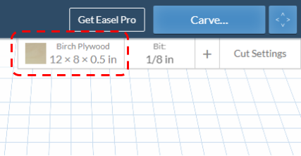
- The first step is to define the workpiece material. Start by clicking on the Materials button in the upper right corner of the Easel window.
- The default material for a new project is a birch plywood, 12 inches long by 8 inches wide by one-half inch thick
|
| Step 2:
|
|
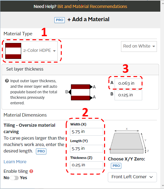
- Use the dropdown menu to select 2-Color HDPE.
- If preferred, you can also match the color to the class workpiece using the second dropdown menu to the right, but it will not affect the cut settings. This example uses red and white for contrast; the class colors will vary.
- Set the Width (X) and Length (Y) to 5.75 inches, and the Thickness (Z) to 0.25 inches
- Set the outer layer thickness in field A to 0.063 inches.
- The inner layer thickness value in field B will be automatically calculated
- Click the Material button again, or click outside the popup window, to close the Material popup window.
|
Set Project Cutting Tool
See also: X-Carve: Easel - Cutters
| Step 1:
|
|
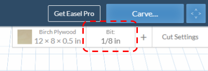
- Once the material has been defined, the next step is to define the cutting tool, or "cutter", which may also called "bit", as Easel does. Start defining the cutting bit by clicking on the Bit button in the upper right corner of the Easel Window.
|
| Step 2:
|
|
- Choose the 1/16 Fishtail Spiral bit from the list.
- If the correct bit is not shown on the list, follow the steps on the cutter page to add it.
- Click the Bit button again, or click outside the popup window, to close the Bit popup window.
|
Set Project Feeds and Speed
See also: X-Carve: Easel - Depths and Speeds
| Step 1:
|
|
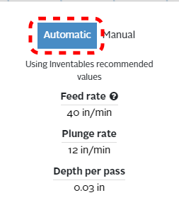
This class will use the default settings for cutting feed rate and spindle speeds, which Easel will set automatically based on the material and cutter choices.
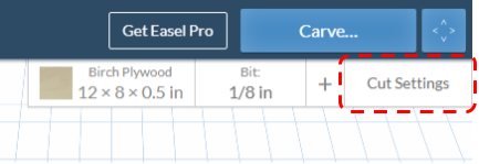
- Click on the Cut Settings button in the upper right corner of the Easel window.
|
| Step 2:
|
|
- Ensure that the Automatic option is highlighted blue by clicking on it.
- Feed settings should be similar to the ones shown at left. If the settings are different, ensure the correct cutting tool was selected.
|
Define Project Geometry and Features
See also: X-Carve: Easel - Geometry, X-Carve: Easel - Features
Each project is built out of a series of gometric shapes, which are used to define the cutting features. Easel uses the terms Shape for geometry, and Cut for features. Easel allows three types of features: profiles, pockets, and drilled holes.
There are three steps in creating the round tuit, and each step uses a different geometry and feature combination.
Profile: Create Outside Circle
| Step 1:
|
|
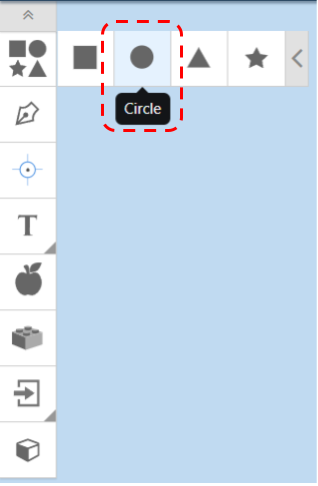
- Start with defining the geometry of the outer shape of the tuit. On the left side of the Easel window, find the Geometry toolbar
- The tool bar may be hidden. Click the grey box with two chevrons in it, in the upper left corner of the Easel window, to show the toolbar.
- Click the top Shapes box to expand the selection of default shapes
- Choose the Circle option, and Easel will insert a circle in your CAM workspace
|
| Step 2:
|
|
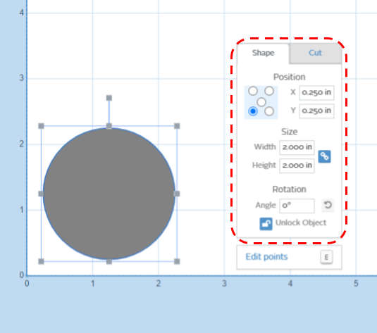
- Once the circle is placed, it can be manipulated using the mouse or the Shape tab in the pop-up window.
- Use the Shape tab to set the circle:
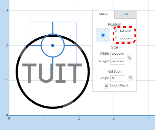
- Find the Position control which looks like you rolled a 5 on a die. Click the lower left corner button
- Set the X Position to 0.250 inches
- Set the Y Position to 0.250 inches
- Set the Width to 2.000 inches
- Set the Height to 2.000 inches
- Set the Angle of rotation to zero degrees
- Click the Lock logo at the bottom to lock the circle in position. This will prevent it from being accidently moved as you work on other parts of the project.
|
| Step 3:
|
|
- Now that the geometry is set, you need to define the feature which will be cut. The default feature is a shallow pocket, as is visible in the simulation portion of the Easel window. Because this is the outside surface of the tuit, you will need to set the feature as a profile which will cut all the way through the part.
- With the circle geometry selected, click on the Cut tab in the popup window
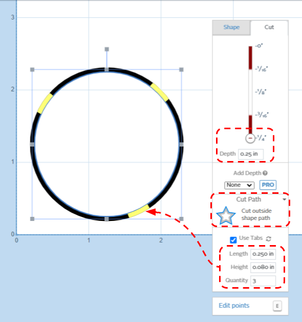
- Use the Cut tab to set the the profile feature:
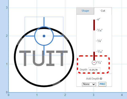
- Set the depth to 0.250 inches
- This can be done either by using the slider, or by typing into into the Depth box
- The Cut Path area currently reads "Cut out a pocket". Click on it, and choose Cut outside shape path
- Because Easel now knows you're cutting your project out of the rest of the workpiece, it will automatically add the Use Tabs box to the bottom of the popup window.
- Ensure the Use Tabs box is checked (it should be on by default)
- The default options for tab Length of 0.250 inches and tab Height of 0.080 inches will work fine
- Set the tab Quantity down to 3
- The tabs are visible in the CAM workspace as yellow bars on the black circle. They can be moved with the mouse by clicking and dragging.
- Tabs will not be shown in the Simulation portion of the Easel window, though they will be present in the tool paths.
|
Pocket: Text
| Step 1:
|
|
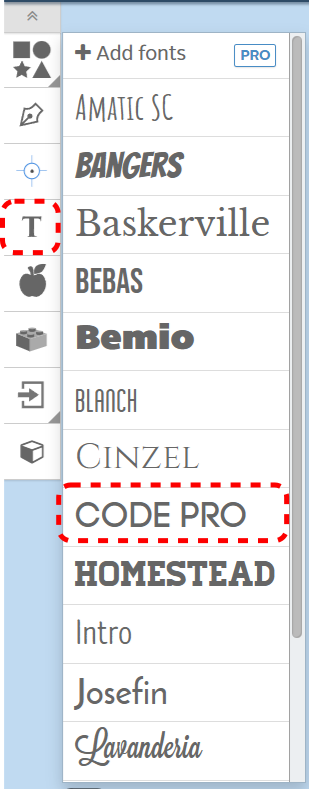
- It's now time to define the text of the tuit. Start by choosing the T (for Text) button on the Geometry toolbar
- The available fonts are shown. For this example, choose CODE PRO from the pop-up window
- "TEXT" will show up on your screen. Don't worry about the size right now. Choose the text, delete the exiting letters, and type TUIT into the text box
|
| Step 2:
|
|
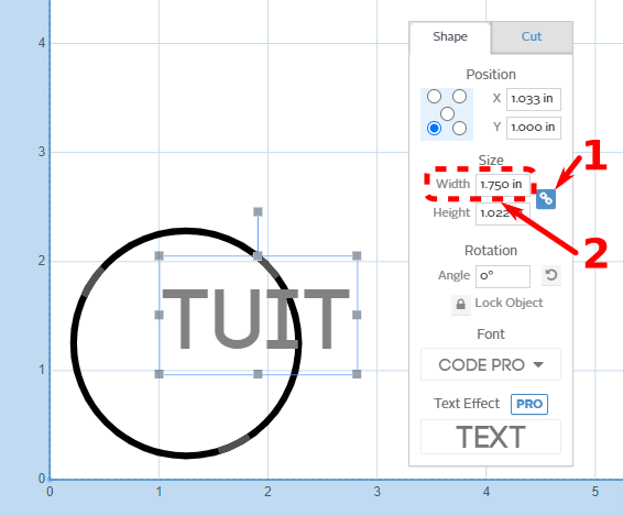
- The text is too large to fit within the outline of the tuit. Start the resizing process by clicking on the text to select it, then click the Link button in the Shape tab of the pop-up window
- The link button ensures that the current ratio of height to width is maintained. Changing either the height or the width will automatically change the other to maintain the same shape proportions
- Change the Width of the text to 1.75 inches to fit within the 2-inch circle of the tuit. The Height will change automatically
- You can try changing the width to 1.25 inches, and noting the effect on the simulation portion on the right of the Easel window. When the text is this small, the currently defined cutting bit (1/16th inch diameter) can't fit into inside the letters. While the text is still visible in the CAM portion of the window on the left, it's gone from the simulation portion on the right
- Return the Width value to 1.75 inches, and the text will reappear in the simulation portion of the window
|
| Step 3:
|
|
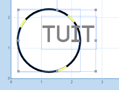
- To center the text, select the text box (if not already selected) by clicking on it
- Hold the Shift key on the keyboard, and select the circle by clicking on it
- The two items may also be selected by dragging a highlight box around all or part of the geometries with the mouse
- The highlight box will select everything it touches, which can result in unintentionally selecting geometries in a crowded area. Use with care!
|
| Step 4:
|
|
- The Geometry Alignment toolbar will appear on the top of the CAM portion of the Easel window. Clicking the Center Horizontally and Center Vertically buttons will place the text in the center of the circle
- In this case, you previously locked the circle in place, so only the text moved. If the circle position had not been locked, both geometries may have moved to allow the alignment
|
| Step 5:
|
|
- Ensure that only the text is selected. Click on the Cut tab of the pop up window
- Changes to feature definitions made in the Cut tab will affect all selected geometries
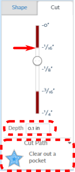
- Set the Depth to 0.1 inches
- The exact depth value is not very important, but it should be deeper than the topmost layer of plastic. The resulting color contrast between the top and middle layers is important for legibility
- The border between the layers is shown on the slider above the depth box, identified by a red arrow in the image to the left
- The Cut Path should be Clear out a pocket by default. If it's not, use the Cut Path dropdown to choose the correct option
|
Drill: Hanging Hole
| Step 1:
|
|
- Now you'll drill a hole in the top of the tuit to hang it on a keychain, wall, or workbench
- The machine will use same cutter to drill the hole as cut pockets and profiles, so it is important the bit be center cutting. The bit chosen at the start of this example is a center cutting bit
- Click the Drill button on the Geometry toolbar. A drill hole geometry will appear in the CAM portion of the Easel window
|
| Step 2:
|
|
- Use the skills you've learned to move the drill hole in an appropriate place on the tuit
- You can click and drag the drill hole anywhere on the tuit
- You can set the the position using the Shape tab values shown to the left, like you did in Step 2 of defining the outside circle
- You can align the hole to the centerline of the tuit at any height, like you did in Steps 3 and 4 of defining the text
|
| Step 3:
|
|
- Once the hole is in the right location, check the Cut tab of the popup window
- Confirm that the hole is being drilled the full depth of the workpiece, or 0.25 inches
|
Checking Toolpaths
| Step 1:
|
|
- Easel automatically creates toolpaths from the features you've previously defined. This is easy, which is good, but it also means you, as the user, have limited control of the process
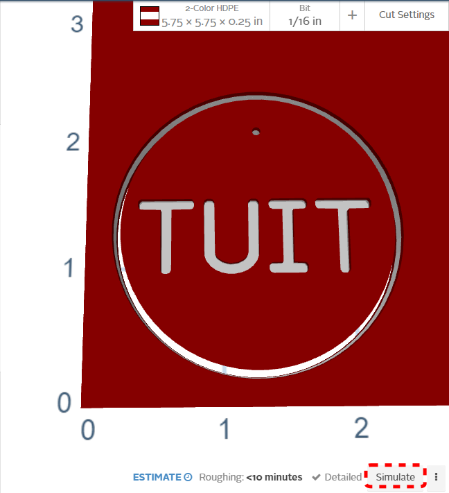
- In the Simulation portion of the Easel window, find and click the Simulate button in the lower right corner
|
| Step 2:
|
|
- Easel will automatically calculate the paths the cutting tool needs to take in order to form the features you've defined.
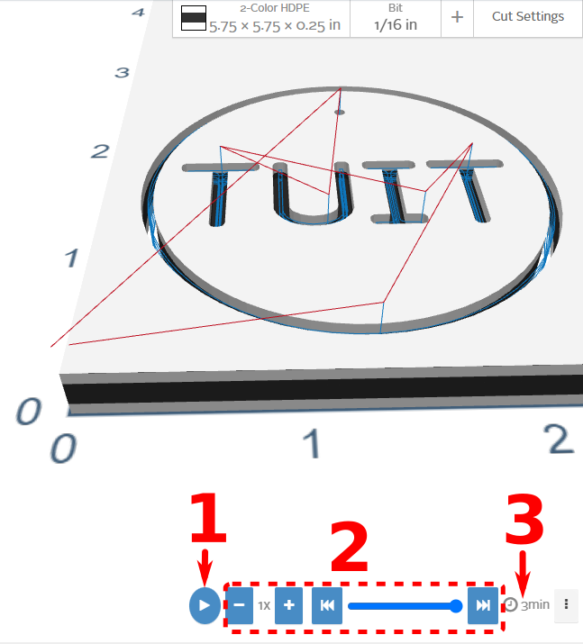
- In the image on the left, the color of the workpiece has been changed to more clearly show the toolpath lines
- Red lines are movements of the X-Carve in rapid mode. Rapid movements are done when the cutting tool is clear of the workpiece, and are relatively high speed
- Note that the red lines start at the 0, 0 origin of the part (lower left corner), and return there at the end of the cutting operations. Keep this in mind when positing clamps on your workpiece
- The rapid speed of the machine can be set by the user, but for the X-Carve, the default is fine
- Blue lines are cutting movements. These are the values set by the Cut settings , which in this example are automatically calculated by Easel based on the size of the cutting bit and the workpiece material
- There are three useful items on the bottom of the screen
- The first item is the Play button. Pressing this button will play through the movements of the machine to cut the tuit
- The second item is is a block of simulation playback controls. Trying the various settings is the fastest way to learn how to use them. They won't affect any of the features, geometry, or cut settings of the tuit, just the simulation
- The third item is a time estimate for cutting your project. In this example, Easel expects the cutting time for the tuit to be about three minutes
|
- That's it, you've completed the programming on your round tuit!
- If you want to, you can cut this project out on the X-Carve as your certification part.
- If you want something more personalized, you can try some of the additional steps below
Personalized Project
To make yourself a personalized certification project, start a new project, create your geometry, and define your features. To keep things fair for everyone in the class, dimensions are limited to 2.5 inches by 2.5 inches. The steps below show you how to start a new project, and a few more methods of creating geometry.
Creating a New Project
| Step 1:
|
|
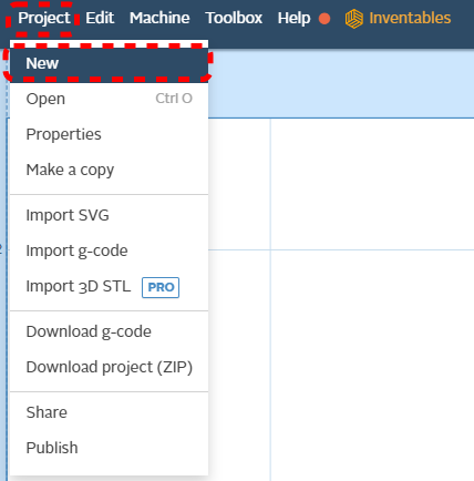
- Start a new project by clicking on the Project menu item in the upper left portion of the Easel window, then choosing New from the dropdown menu
- Rename the new project by clicking on the Untitled block in the upper left portion of the Easel window
|
| Step 2:
|
|
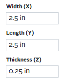
- Define the material in the same way you did above, but this time the Width (X) and Length (Y) will both be 2.5 inches
- Set the cutting bit as the 1/16 Fishtail
- Set the cut settings to Automatic
|
Geometry: Easel Design Library
| Step 1:
|
|
- Click on the apple-shaped Pro Design Library icon in the Geometry Toolbar, on the left of the Easel window
- The Easel library of shapes will show in a popup window
|
| Step 2:
|
|
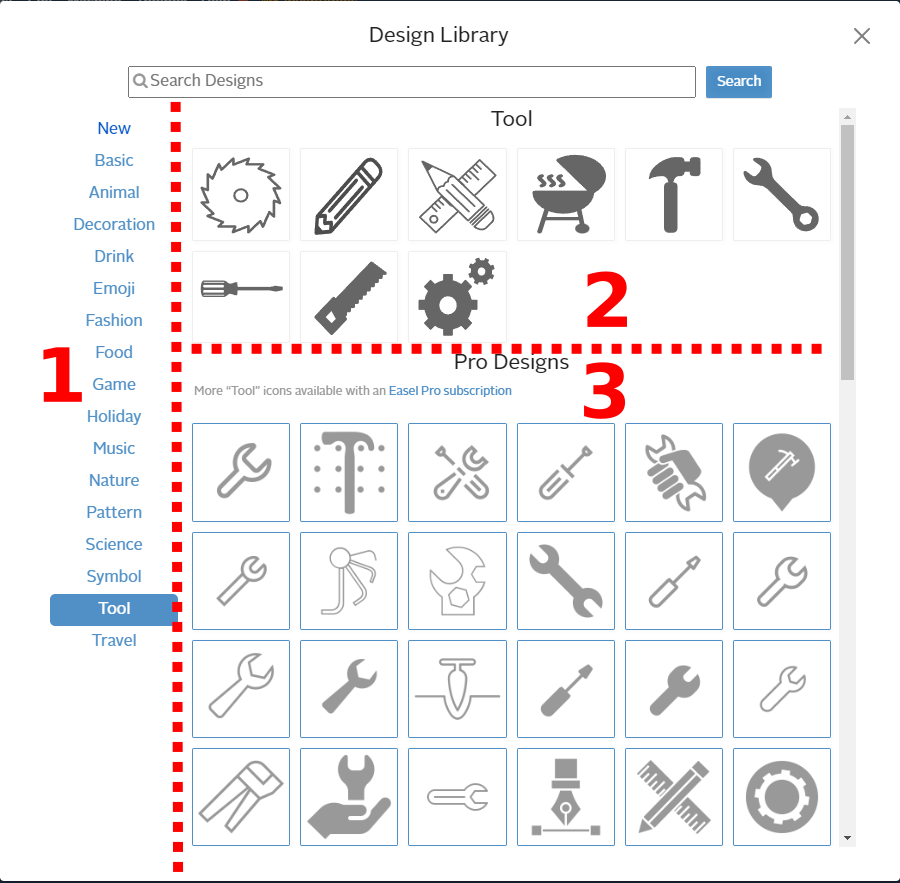
- There is a list of shape categories on the left side of the popup window
- There are Basic shapes on the top of the screen. These are shapes that are available to everyone with an Easel account
- There are Pro Designs on the bottom of the screen. These shapes are only available to users with a paid Easel Pro account
- For this example, the Tools category was selected. Clicking on the hammer shape will bring you to the next screen
|
| Step 3:
|
|
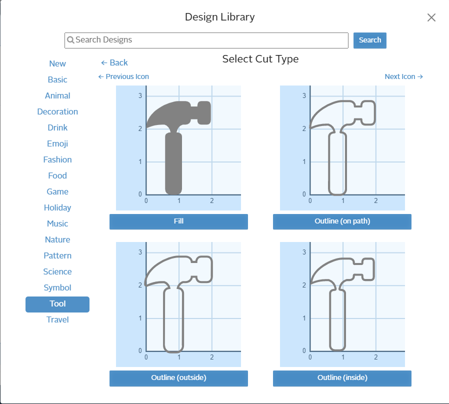
- The second screen allows you to set the feature type by choosing one of the options. The top left option, "Fill", is the same as "Cut out a pocket" in the Cut tab of the CAM workspace popup window
- The feature type can be changed later through the Cut tab of the CAM workspace popup window
- Click the Fill button insert the shape into the CAM workspace
|
Geometry: Zero Depth Pockets
| Step 1:
|
|
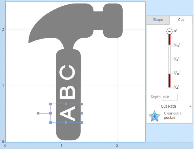
- After resizing the hammer-shaped pocket to fit on the workpiece, a set of text pockets were added
- The letters were added as individual text geometries to allow spacing to be increased; otherwise, the cutting tool can't fit between them
- The letters were moved into place on the hammer handle, and the feature depth on the Cut tab of the popup window was set to zero
|
| Step 2:
|
|
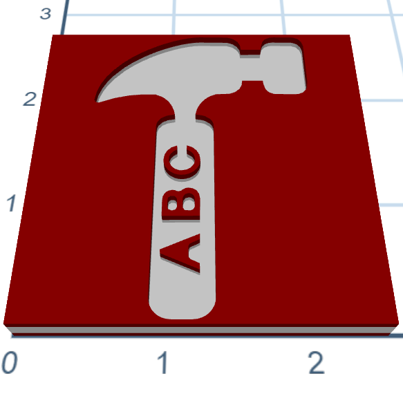
- The zero depth of the letters makes Easel cut around them, resulting in raised lettering in the hammer-shaped pocket feature
- Note that there are limits to this method:
- Features have to be robust enough to hold up to cutting forces. Thin, tall features (such as lettering) may break off during machining
- The features have to be large enough for the cutting tool to create them. The lack of a hole in the A shows that this geometry is too small to fit the cutting tool
|
Geometry: Importing Raster Images
| Step 1:
|
|
- Easel can import a variety of files. The most common ones are image files, which are shown below. The process is different for raster or vector files.
- Raster graphics files, such as .BMP, .GIF, JPEG, and .PNG files, require interpretation as part of the import process
- Vector graphics files, such as .SVG, import directly into Easel
- Easel will also import CAD drawings or pre-programmed G-code. The process is similar, but not addressed by this example.
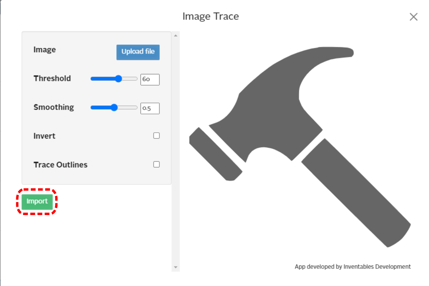
- For practice, try importing the hammer icon (a .PNG raster image) to the left
- Right click on the image, and choose "Save Image As"
- Save the file to your computer, in a location where you'll be able to find it later
|
| Step 2:
|
|
- Find the Import button on the Geometry toolbar, on the left of the Easel window.
- Choose Image Trace from the menu.
|
| Step 3:
|
|
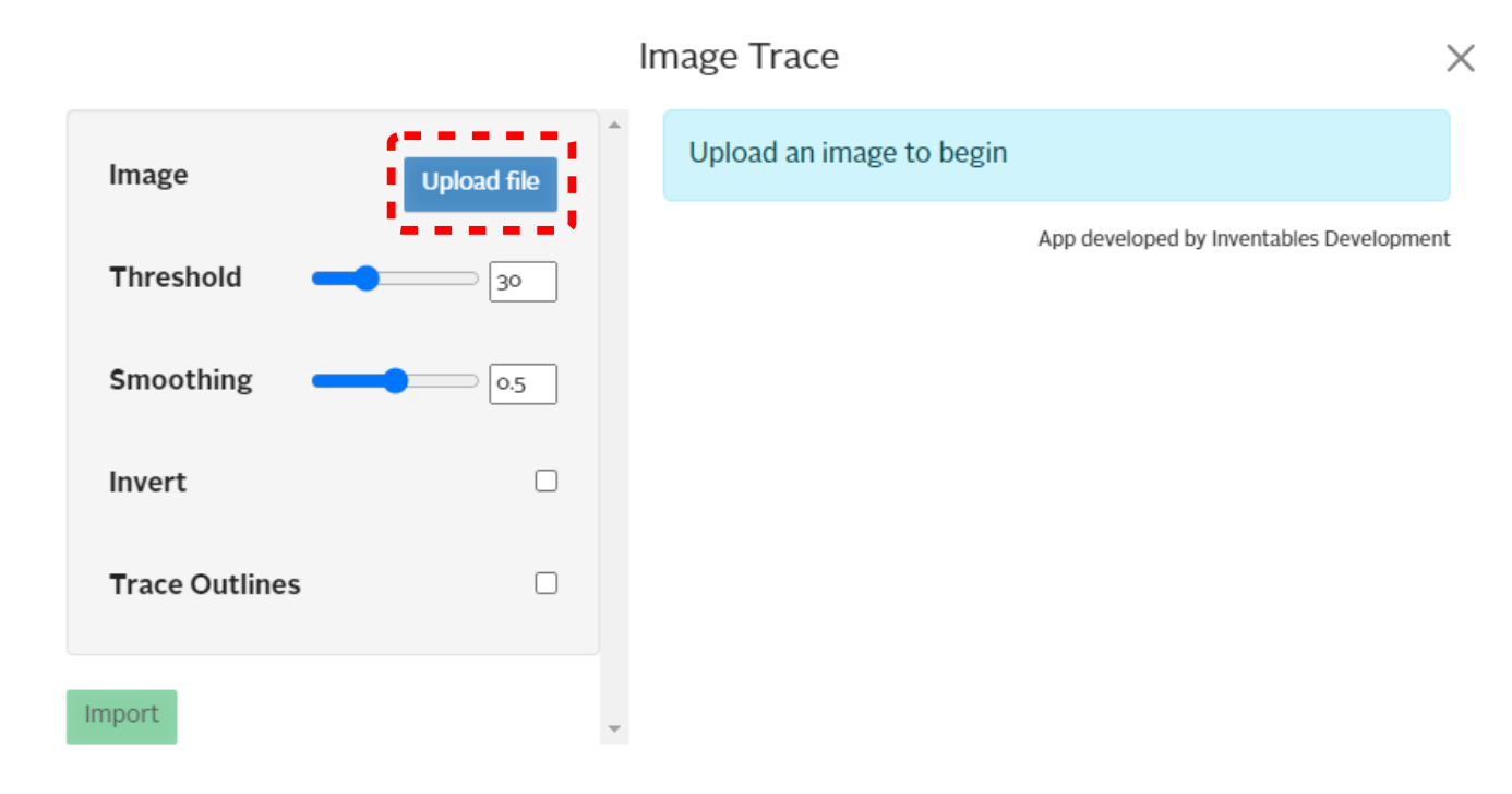
- In the popup window, click on the Upload file button
|
| Step 4:
|
|
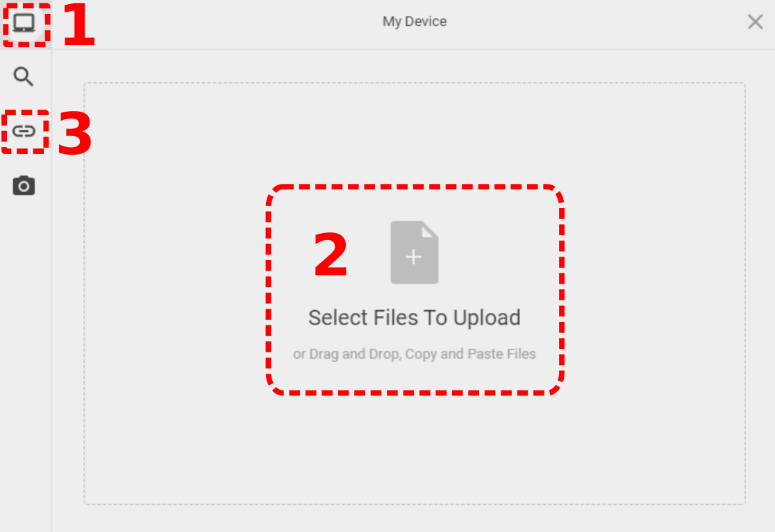
- The file selection popup window will default to your computer, showing My Device at the top of the screen
- Click on Select Files to Upload to open a file selection window
- Navigate to where you previously saved the hammer icon, and select the file to upload
- If you can't find the file, choose the Link (URL) icon on the left of the popup window
- Copy the URL below into the URL field, and click the blue button:
https://wiki.sparkmakerspace.org/images/e/e4/WS_X-Carve_ClassImageExampleHammer.png
|
| Step 5:
|
|
- Once the file has been uploaded, Easel will try to trace the shape outline so the resulting geometry can be put into the CAM workspace
- The hammer icon is easy for Easel to interpret, because it's a dark outline on a white background with sharp delineation between the two
- More complex images, with lots of greys or colors, will be more difficult to import
- Images without enough contrast between the subject and the background may show as a uniform grey field during import
- There are four settings which can be adjusted prior to importation.
- Threshold defines how much contrast is required is required between the subject and the background before Easel draws a separating line. A higher threshold value requires more contrast with the background
- Smoothing defines how sharp the corners of the lines are. A lower smoothing value gives sharper corners
- Invert reverses Easel's choice of subject and background
- Trace Outlines removes any filled areas
- Adjust the sliders to get some experience with the way Easel does the interpretation
- Note that a grey Loading... tag will show in the upper right corner of the popup window while Easel is working
- Wait until the Loading tag goes away before making more adjustments
- When you are happy with the trace, click the green Import button
|
| Step 4:
|
|
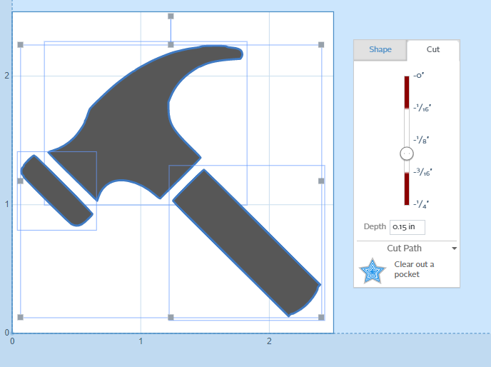
- Easel will insert the result into the CAM workspace
- The image at left shows the result, after being resized to fit the workpiece
- Note that each piece of the hammer icon was imported as a sperate geometry, and can be defined using different feature, if you desire
- It also means that the pieces can be moved relative to each other, so watch out in complex images with many tiny features - it's easy to get them displaced
|
Geometry: Importing Vector (.SVG) Images
| Step 1:
|
|
- As noted above, Vector graphics files import directly into Easel, but Easel is limited to .SVG files
- To practice importing an .SVG file, press and hold shift on your keyboard while clicking on the icon to the left.
- A copy of the original hammer icon file will open in a new window
- Right click on the file, and choose Save As to save the file
- Choose an easy to find place on your computer to save the file for use in a couple of steps
|
| Step 2:
|
|
- Find the Import button on the Geometry toolbar, on the left of the Easel window.
- Choose SVG from the menu.
- A file selection window will open
- Navigate to where you previously saved the hammer icon .SVG file, and select the file to import
|
| Step 3:
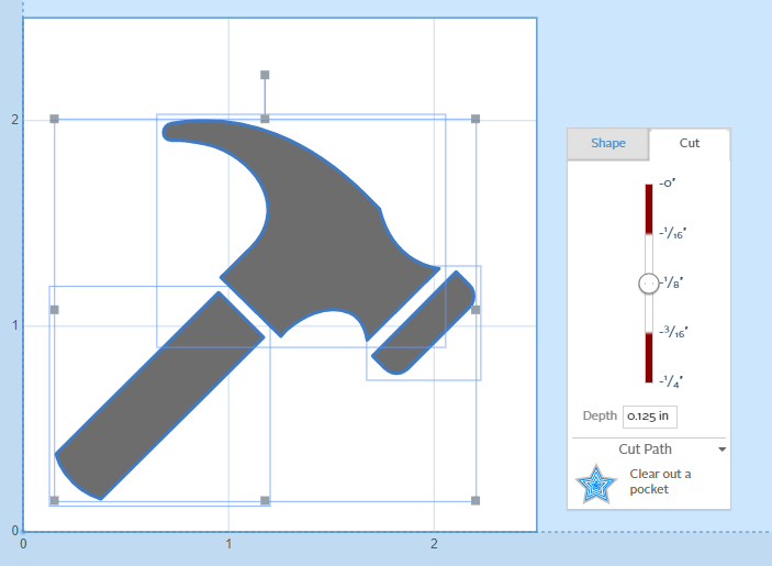
|
|
- The imported geometry may need to be resized to your workpiece, as shown to the left
- As with the raster image import, each piece of the hammer icon was imported as a sperate geometry, and can be defined using different features
|
Customize Your Project
Using the methods above, you can make your own custom shape, text, and hole patterns. Any project that meets the following requirements can be cut as part of the class:
- Use the 1/16-inch fishtail cutting tool
- Uses Easel automatic cut settings
- Use 1/4-inch HDPE material, as defined above
- Use material size limits of 2.5-inch width and length
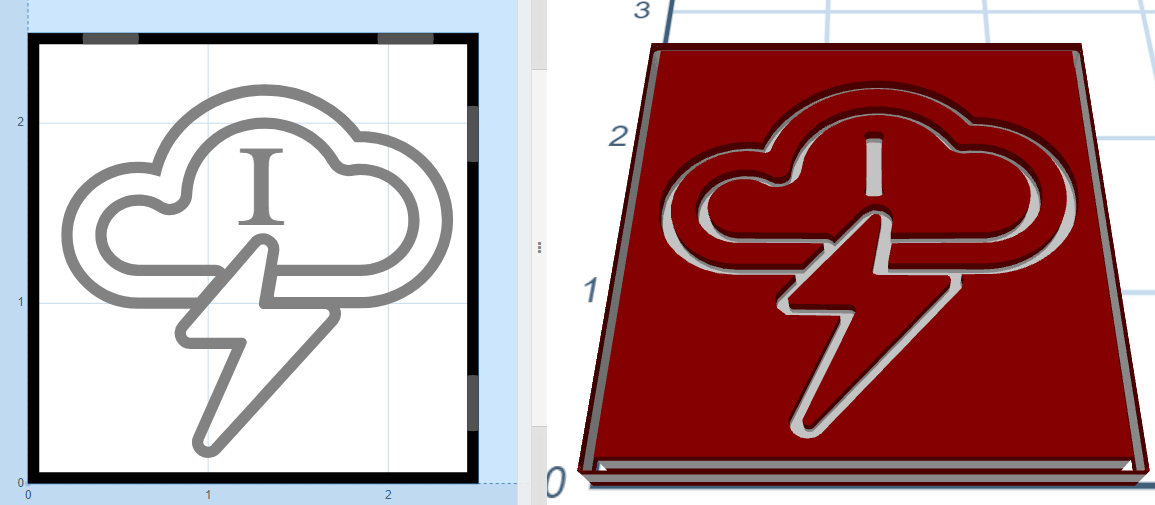
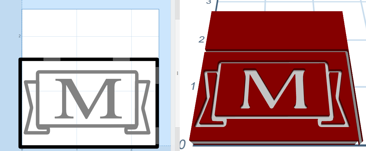
Some examples are shown below.
Done?
If you have completed your project programming, and are ready to move on to setting up the machine for cutting, go to Part 2: Machine Setup.
