Difference between revisions of "X-Carve: Example Geometry"
Jump to navigation
Jump to search
| Line 70: | Line 70: | ||
|} | |} | ||
| − | ==Define Project Geometry and Features | + | ==Define Project Geometry and Features== |
''See also: [[X-Carve: Easel - Geometry]], [[X-Carve: Easel - Features]]'' | ''See also: [[X-Carve: Easel - Geometry]], [[X-Carve: Easel - Features]]'' | ||
| Line 77: | Line 77: | ||
There are three steps in creating the round tuit, and each step uses a different feature. | There are three steps in creating the round tuit, and each step uses a different feature. | ||
| − | ===Outside Circle=== | + | ===Profile: Create Outside Circle=== |
{| class="wikitable" | {| class="wikitable" | ||
| Line 120: | Line 120: | ||
| − | ===Text=== | + | ===Pocket: Text=== |
{| class="wikitable" | {| class="wikitable" | ||
| Line 127: | Line 127: | ||
|[[file:WS X-carve ClassGeometryFontsMarkup.png|x448px|center|border]] | |[[file:WS X-carve ClassGeometryFontsMarkup.png|x448px|center|border]] | ||
| | | | ||
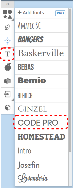
| − | # It's now time to define the text of the tuit. Start by choosing the '''T''' (for '''Text''')button on the Geometry toolbar | + | # It's now time to define the text of the tuit. Start by choosing the '''T''' (for '''Text''')button on the Geometry toolbar |
| − | # The available fonts are shown. For this example, choose '''CODE PRO''' from the pop-up window | + | # The available fonts are shown. For this example, choose '''CODE PRO''' from the pop-up window |
| − | # TEXT will show up on your screen. Don't worry about the size right now. Choose the test, delete the exiting letters, and type '''TUIT''' in the text box | + | # TEXT will show up on your screen. Don't worry about the size right now. Choose the test, delete the exiting letters, and type '''TUIT''' in the text box |
|- | |- | ||
! scope="row" | Step 2: | ! scope="row" | Step 2: | ||
| [[file:WS X-Carve ClassTextGeometryMarkup.png|center]] | | [[file:WS X-Carve ClassTextGeometryMarkup.png|center]] | ||
| | | | ||
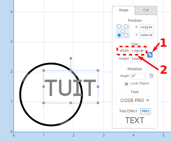
| − | # The text is too large to fit within the outline of the tuit. Start the resizing process by clicking on the text to select it, then click the '''Link button''' in the Shape tab of the pop-up window | + | # The text is too large to fit within the outline of the tuit. Start the resizing process by clicking on the text to select it, then click the '''Link button''' in the Shape tab of the pop-up window |
| − | #* The link button ensures that the current ratio of height to width is maintained. Changing either the height or the width will automatically change the other to maintain the same proportions | + | #* The link button ensures that the current ratio of height to width is maintained. Changing either the height or the width will automatically change the other to maintain the same proportions |
| − | # Change the Width of the text to '''1.75 inches''' to fit within the 2-inch circle of the tuit. The Height will change | + | # Change the Width of the text to '''1.75 inches''' to fit within the 2-inch circle of the tuit. The Height will change |
| − | #* You can try changing the width to 1.25 inches, and noting the effect on the simulation portion on the right of the Easel window. When the text is this small, the currently defined cutting bit can't fit into inside the letters, except for in a few locations. While the text is still visible in the CAM portion of the window on the left, it's gone from the simulation portion on the right | + | #* You can try changing the width to 1.25 inches, and noting the effect on the simulation portion on the right of the Easel window. When the text is this small, the currently defined cutting bit can't fit into inside the letters, except for in a few locations. While the text is still visible in the CAM portion of the window on the left, it's gone from the simulation portion on the right |
| − | #* Return the Width value to 1.75 inches, and the text will reappear in the simulation portion of the window | + | #* Return the Width value to 1.75 inches, and the text will reappear in the simulation portion of the window |
|- | |- | ||
! scope="row" | Step 3: | ! scope="row" | Step 3: | ||
|[[file:WS X-Carve ClassGeometriesSelected.png |center]] | |[[file:WS X-Carve ClassGeometriesSelected.png |center]] | ||
| | | | ||
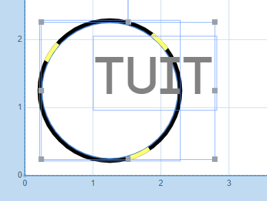
| − | # To center the text, select the text box (if not already selected) by clicking on it | + | # To center the text, select the text box (if not already selected) by clicking on it |
| − | # Hold the '''Shift''' key on the keyboard, and select the circle by clicking on it | + | # Hold the '''Shift''' key on the keyboard, and select the circle by clicking on it |
| − | #* The two items may also be selected by dragging a highlight box around all or part of the geometries with the mouse | + | #* The two items may also be selected by dragging a highlight box around all or part of the geometries with the mouse |
#* The highlight box will select everything it touches, which can result in unintentionally selecting geometries in a crowded area. Use with care! | #* The highlight box will select everything it touches, which can result in unintentionally selecting geometries in a crowded area. Use with care! | ||
|- | |- | ||
| Line 151: | Line 151: | ||
|[[file:WS X-Carve GeometryAlignmentToolbarMarkup.png|center]] | |[[file:WS X-Carve GeometryAlignmentToolbarMarkup.png|center]] | ||
| | | | ||
| − | # The Geometry Alignment toolbar will appear on the top of the CAM portion of the Easel window. Clicking the '''Center Horizontally''' and '''Center Vertically''' buttons will place the text in the center of the circle | + | # The Geometry Alignment toolbar will appear on the top of the CAM portion of the Easel window. Clicking the '''Center Horizontally''' and '''Center Vertically''' buttons will place the text in the center of the circle |
| − | #* In this case, you previously locked the circle in place, so only the text moved. If the circle position had not been locked, both geometries may have moved to allow the alignment | + | #* In this case, you previously locked the circle in place, so only the text moved. If the circle position had not been locked, both geometries may have moved to allow the alignment |
|- | |- | ||
! scope="row" | Step 5: | ! scope="row" | Step 5: | ||
| [[file:WS X-Carve ClassTextFeatureMarkup.png|center]] | | [[file:WS X-Carve ClassTextFeatureMarkup.png|center]] | ||
| | | | ||
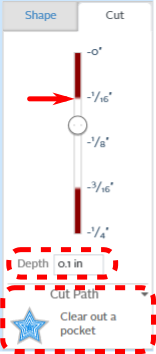
| − | # Ensure that only the text is selected. Click on the '''Cut''' tab of the pop up window | + | # Ensure that only the text is selected. Click on the '''Cut''' tab of the pop up window |
| − | #* Changes to feature definitions made in the Cut tab will affect all selected geometries | + | #* Changes to feature definitions made in the Cut tab will affect all selected geometries |
# Set the Depth to '''0.1 inches''' | # Set the Depth to '''0.1 inches''' | ||
| − | #* The exact depth value is not very important, but it should be deeper than the topmost layer of plastic. The resulting color contrast between the top and middle layers is important for legibility | + | #* The exact depth value is not very important, but it should be deeper than the topmost layer of plastic. The resulting color contrast between the top and middle layers is important for legibility |
| − | #*The border between the layers is shown on the slider above the depth box, identified by a red arrow in the image to the left | + | #*The border between the layers is shown on the slider above the depth box, identified by a red arrow in the image to the left |
| − | # The Cut Path should be '''Clear out a pocket''' by default. If it's not, use the Cut Path dropdown to choose the correct option. | + | # The Cut Path should be '''Clear out a pocket''' by default. If it's not, use the Cut Path dropdown to choose the correct option |
| + | |} | ||
| + | |||
| + | ===Drill: Hanging Hole=== | ||
| + | |||
| + | {| class="wikitable" | ||
| + | |- | ||
| + | ! scope="row" | Step 1: | ||
| + | |[[file:WS X-Carve ClassGeometryDrillMarkup.png|x400px|center|border]] | ||
| + | | | ||
| + | # Now you'll drill a hole in the top of the tuit to hang it on a keychain, wall, or workbench | ||
| + | # *The machine will use same cutter to drill the hole as cut pockets and profiles, so it is important the bit be center cutting. The bit chosen at the start of this example is a center cutting bit | ||
| + | # Click the '''Drill''' button on the Geometry toolbar. A drill hole geometry will appear in the CAM portion of the Easel window | ||
| + | |- | ||
| + | ! scope="row" | Step 2: | ||
| + | | [[file:WS X-Carve ClassDrillGeometryMarkup.png|center]] | ||
| + | | | ||
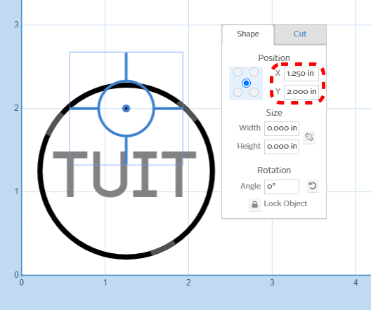
| + | # Use the skills you've learned to move the drill hole in an appropriate place on the tuit | ||
| + | #* You can click and drag the drill hole anywhere on the tuit | ||
| + | #* You can choose the position shown to the left, like you did in Step 2 of defining the outside circle | ||
| + | #* You can align the hole to the centerline of the tuit at any height, like you did in Steps 3 and 4 of defining the text | ||
| + | |- | ||
| + | ! scope="row" | Step 3: | ||
| + | |[[file:WS X-Carve ClassDrillFeatureMarkup.png|center]] | ||
| + | | | ||
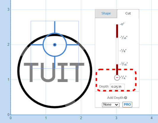
| + | # Once the hole is in the right location, check the Cut tab of the popup window | ||
| + | # Confirm that the hole is being drilled the full depth of the workpiece, or '''0.25 inches''' | ||
| + | |} | ||
| + | |||
| + | ==Checking Toolpaths== | ||
| + | |||
| + | {| class="wikitable" | ||
| + | |- | ||
| + | ! scope="row" | Step 1: | ||
| + | |[[file:WS X-Carve ClassSimulateViewMarkup.png|center|border]] | ||
| + | | | ||
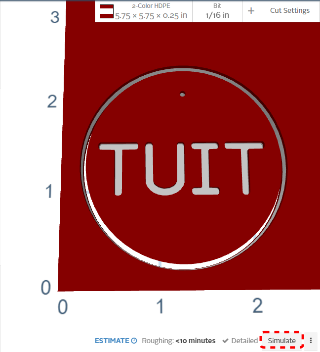
| + | # Easel automatically creates toolpaths from the features you've previously defined. This is easy, which is good, but it also means you, as the user, have limited control of the process | ||
| + | # In the Simulation portion of the Easel window, find and click the '''Simulate''' button in the lower right corner | ||
| + | |- | ||
| + | ! scope="row" | Step 2: | ||
| + | | [[file:WS X-Carve ClassSimulateToolpathsMarkup.png|center]] | ||
| + | | | ||
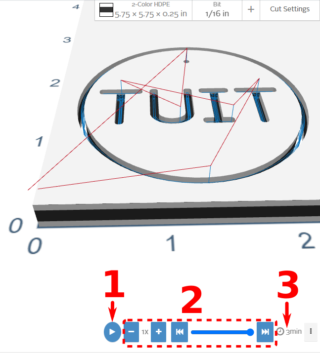
| + | # Easel will automatically calculate the paths the cutting tool needs to take in order to form the features you've defined. | ||
| + | #* In the image on the left, the color of the workpiece has been changed to more clearly show the toolpath lines | ||
| + | #* Red lines are movements of the X-Carve in '''rapid''' mode. Rapid movements are done when the cutting tool is clear of the workpiece, and are relatively high speed | ||
| + | #** Note that the red lines start at the 0, 0 origin of the part (lower left corner), and return there at the end of the cutting operations. Keep this in mind when positing clamps on your workpiece | ||
| + | #**The rapid speed of the machine can be set by the user, but for the X-Carve, the default is fine | ||
| + | #* Blue lines are cutting movements. These are the values set by the '''Feeds and Speeds''' settings, which in this example are automatically calculated by Easel based on the size of the cutting bit and the workpiece material | ||
| + | # There are three useful items on the bottom of the screen | ||
| + | ## The first item is the '''Play''' button. Pressing this button will play through the movements of the machine to cut the tuit | ||
| + | ## The second item is is a block of simulation playback controls. Trying the various settings is the fastest way to learn how to use them. They won't affect any of the features, geometry, or cut settings of the tuit, just the simulation | ||
| + | ## The third item is a time estimate for cutting your project. In this example, Easel expects the cutting time for the tuit to be about three minutes | ||
|} | |} | ||
Revision as of 23:09, 18 February 2023
This tutorial will guide a new user through the basic steps of using the X-Carve Router. The project will be a small round tuit out of multi-color HDPE plastic.
Start A New Project
See also: X-Carve: Easel
- If you haven't already, create an Easel account by following the steps on X-Carve: Easel page.
- Make sure to set up the Spark X-Carve in the new account
- Go to https://easel.inventables.com/users/sign_in and sign in
- Start a new project using the green button in the upper right of the Easel Start Screen
- Easel will bring you to the Easel Main Screen
Define Project Material
See also: X-Carve: Easel - Materials
| Step 1: |
| |
|---|---|---|
| Step 2: |
|
Set Project Cutting Bit
See also: X-Carve: Easel - Cutters
| Step 1: |
| |
|---|---|---|
| Step 2: |
|
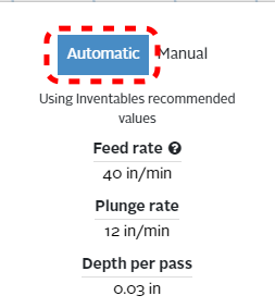
Set Project Feeds and Speed
See also: X-Carve: Easel - Depths and Speeds
| Step 1: |
| |
|---|---|---|
| Step 2: |
|
Define Project Geometry and Features
See also: X-Carve: Easel - Geometry, X-Carve: Easel - Features
Each project is built out of a series of gometric shapes, which are used to define the cutting features. Easel uses the terms Shape for geometry, and Cut for features. Easel allows three types of features: profiles, pockets, and drilled holes.
There are three steps in creating the round tuit, and each step uses a different feature.
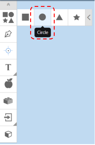
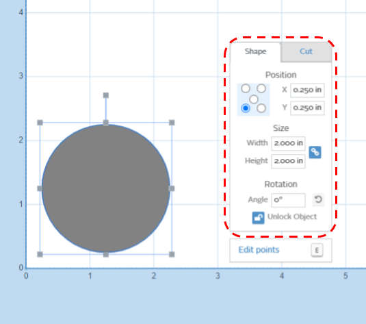
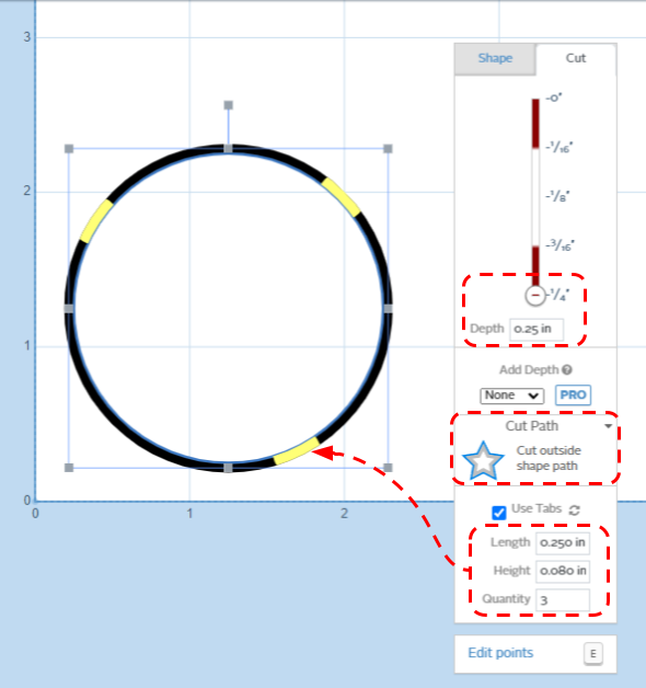
Profile: Create Outside Circle
| Step 1: |
| |
|---|---|---|
| Step 2: |
| |
| Step 3: |
|
Pocket: Text
| Step 1: |
| |
|---|---|---|
| Step 2: |
| |
| Step 3: |
| |
| Step 4: |
| |
| Step 5: |
|
Drill: Hanging Hole
| Step 1: |
| |
|---|---|---|
| Step 2: |
| |
| Step 3: |
|
Checking Toolpaths
| Step 1: |
| |
|---|---|---|
| Step 2: |
|
