X-Carve: Example Carve
This tutorial is Part 3 of the X-Carve Router practice example. This portion of the example will explain how to set up the coordinates for your carve, and carve your example part. If you haven't yet, go complete Part 1 and Part 2 first.
| Login to Easel and Start a New Project |
| Part 1: Creating Geometry and Features |
| Part 2: Setting Up the Machine |
| Part 3: Carving the Part |
Connecting the Computer to the Controller
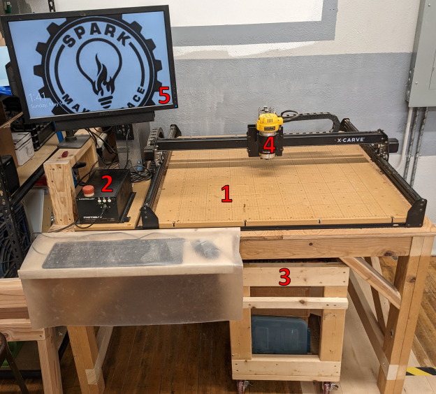
Only the computer in the Woodshop should be used to run X-Carve programs. It is freely accessible for any members with Woodshop Access.
| Step 1: |
Log into the computer using following credentials:
| |
|---|---|---|
| Step 2: |
| |
| Step 3: |
|
Homing and Jogging The Machine
You're almost ready to cut your project on the X-Carve. Before you get to carving, there's a few things you'll need to know about controlling the X-Carve spindle position using the computer.
KEEP HANDS AND FINGERS CLEAR OF THE X-CARVE WHEN IT IS OPERATING
| Step 1: |
There are two buttons in the upper right corner of the Easel window. Depending on the state of the X-Carve controller, they may be blue or green. If the buttons are blue, the X-Carve controller is not connected to the computer.
| |
|---|---|---|
| Step 2: |
Once the buttons have turned green, the X-Carve controller is correctly connected to the computer. The Carve... button will be used later. Right now, click the button with four arrows to open the Jog controls. | |
| Step 3: |
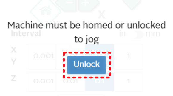
Easel will ask you to unlock the machine prior to allowing access to the jog controls. Be aware that the machine can start moving by itself from this point forward. Keep hands, fingers, etc. clear of the machine table. Click the Unlock button to access the jog control panel. | |
| Step 4: |
Jogging is a method of moving the spindle manually, by directly controlling the machine motors. Jogging the machine does not respect the limit switches. The machine will follow user directions, even when it will damage the machine. Users must use the jog commands carefully and responsibly to prevent breaking the X-Carve. The Jog Machine panel has several sections, which are described in additional detail below. Two general controls should be mentioned first, however.
| |
| Step 5: |
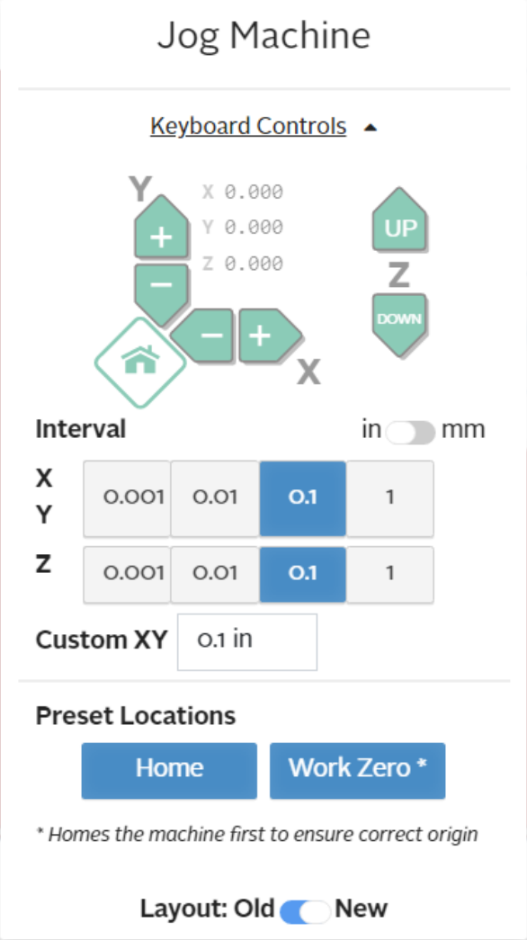
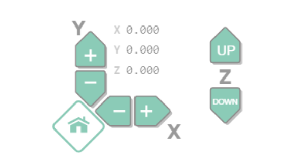
The first part of the jog panel shows the buttons for direction controls. Each set of arrow buttons control a single axis.
Also shown is a set of coordinates on all three axes. In this image at left, the machine is in the Home position, and all three coordinate values are zero. Clicking the arrow buttons for each axis will move the spindle in the associated direction. Care should be taken when near the edges of the table to prevent exceeding the limits of machine travel. | |
| Step 6: |
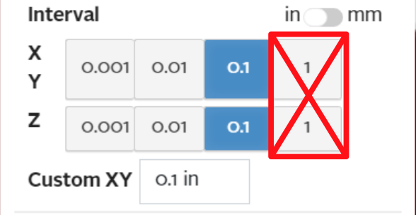
The next part of the jog panel shows the options for travel rate, or interval. The interval is the distance traveled by the spindle for each click on one of the directional controls. The standard settings are factors of 10 in inches, but the interval can be set in to millimeters, or set for custom interval values. Due to control issues, users are advised to use only the lower three settings. The travel rate, particularly in the Z-axis, using the highest setting is dangerous for the machine. | |
| Step 7: |
The last portion of the jog panel has two buttons on it.
|
