Difference between revisions of "X-Carve: Example Carve"
| Line 139: | Line 139: | ||
|- | |- | ||
! scope="row" | Step 1: | ! scope="row" | Step 1: | ||
| − | |[[file:|center]] | + | |[[file:WS X-Carve CarveButton.png|center]] |
| | | | ||
| − | Press the Carve | + | Press the '''Carve...''' button in the upper right corner of the Easel window. |
|- | |- | ||
! scope="row" | Step 2: | ! scope="row" | Step 2: | ||
| | | | ||
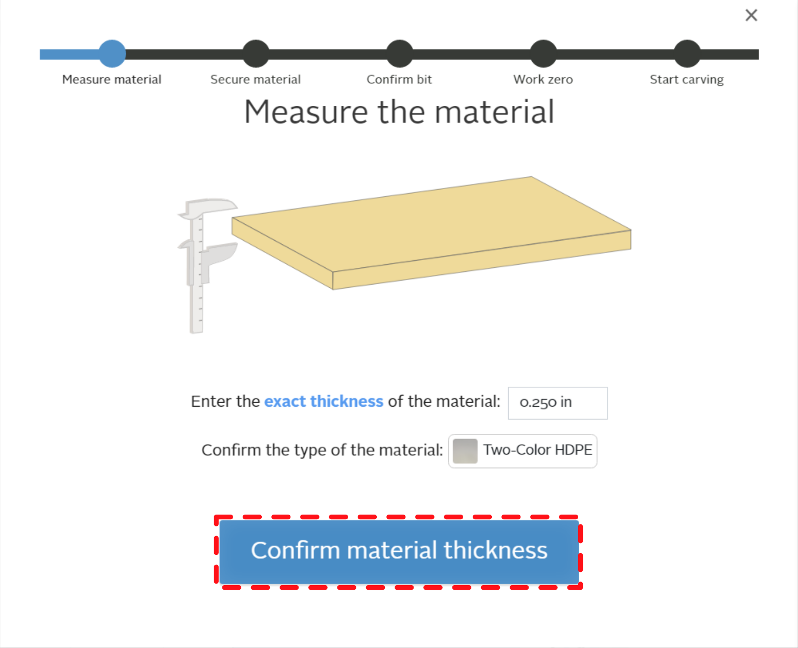
| − | [[File:|center]] | + | [[File:WS X-Carve CarveMeasure.png|400px|center]] |
| | | | ||
| − | Confirm | + | * Confirm the '''thickness''' of the workpiece is correct. It should match the project material defined in [[X-Carve: Example Geometry |Part 1]] |
| + | * Confirm the type of '''material''' is correct. It should match your workpiece, and the project material defined in [[X-Carve: Example Geometry |Part 1]] | ||
| + | * If material thickness and type are both correct, click the blue '''Confirm material thickness''' button | ||
|- | |- | ||
! scope="row" | Step 3: | ! scope="row" | Step 3: | ||
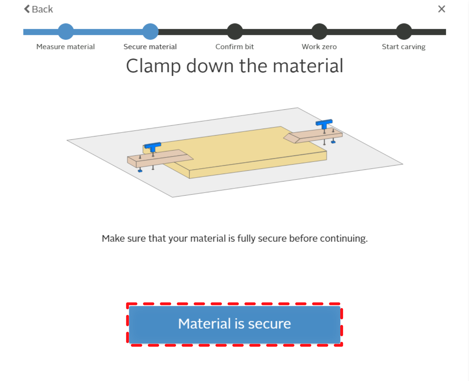
| − | |[[file:| | + | |[[file:WX X-Carve CarveClampMarkup.png|400px|center]] |
| | | | ||
| − | Confirm | + | * Confirm the workpiece is securely '''clamped''' down. |
| + | ** Reach over, give it a shove, and make sure it doesn't wiggle. | ||
| + | ** If it's not secure, go back to [[X-Carve: Example Machine Setup|Part 2]] and clamp it down snug. | ||
| + | * If it is secure, click on the blue '''Material is secure''' button. | ||
| + | |||
|- | |- | ||
! scope="row" | Step 4: | ! scope="row" | Step 4: | ||
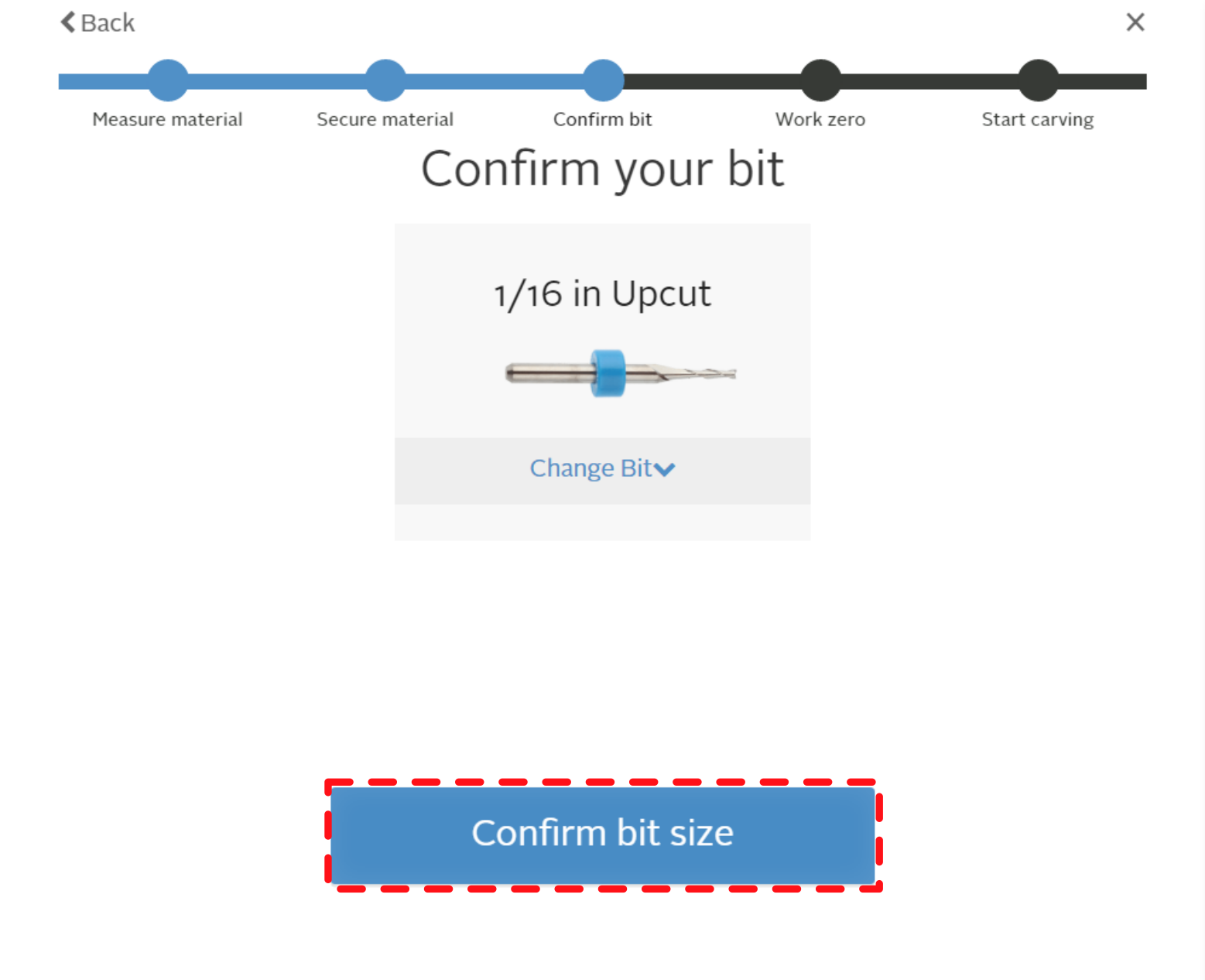
| − | |[[file:| | + | |[[file:WS X-Carve CarveConfirmBitMarkup.png|400px|center]] |
| | | | ||
| − | Confirm bit is correct and | + | * Confirm that the '''correct bit''' is installed in the the spindle router. |
| + | ** If the cutting bit in the spindle is correct, but the image on the screen is wrong, go back to [[X-Carve: Example Geometry |Part 1]] to correct it. | ||
| + | *** It it possible to change the bit definition in this screen if the diameter does not change, and you're using the Easel automatic feeds and speeds. | ||
| + | ** If the cutting bit on the screen is correct, but doesn't match the one in the spindle router, go back to [[X-Carve: Example Machine Setup|Part 2]] to install the correct bit. | ||
| + | * If the cutting bit in the spindle router matches the cutting bit on the screen, click the blue '''Confirm bit size''' button | ||
|- | |- | ||
|} | |} | ||
| − | === Setting Work Zero: Probe === | + | === Setting Work Zero === |
| + | Defining the '''work zero''' means telling the X-Carve where the tip of the cutting bit is, and where the workpiece is. There are two was to do with: with the Z-axis probe, and by manually touching the tip of the cutting bit to the corner of the workpiece. Using the probe is usually faster and more accurate. It is also less likely to break or damage very small cutting bits. For this example, Spark recommends using the probe, but both methods are described below. | ||
| + | |||
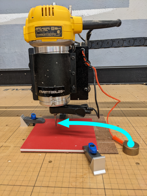
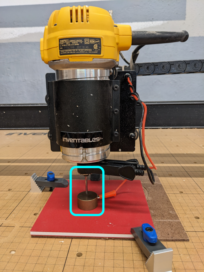
| + | The Z-probe is three pieces, connected by wires. There is a barrel plug, with one black wire and one red wire coming out. The black wire connects to a spring clip. The red wire connects to a brass touch plate. The Z-probe should be stored in the cart tool tray when not in use. | ||
| + | |||
| + | ==== Probe Work Zero ==== | ||
| + | |||
{| class="wikitable" | {| class="wikitable" | ||
|- | |- | ||
! scope="row" | Step 1: | ! scope="row" | Step 1: | ||
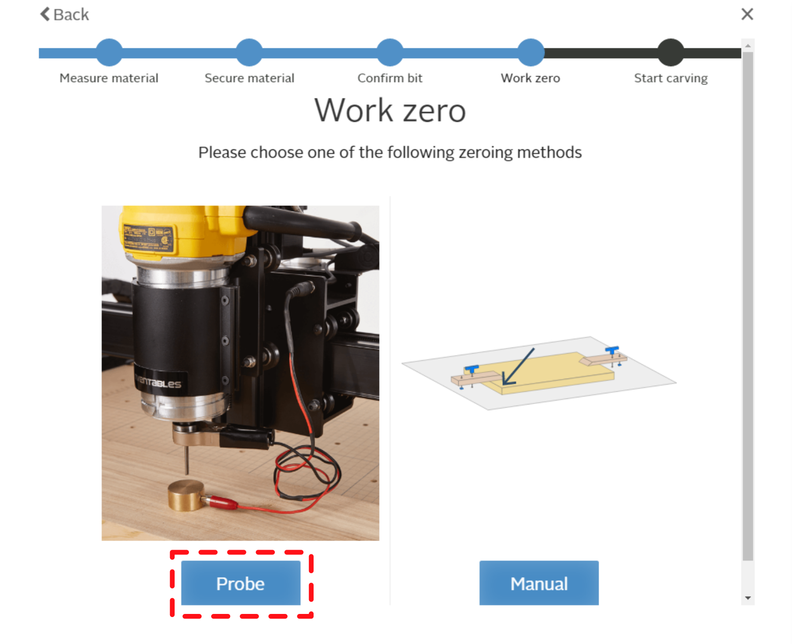
| − | |[[file:|center]] | + | |[[file:WS X-Carve CarveWorkZeroChoiceProbeMarkup.png|400px|center]] |
| | | | ||
| − | + | * Click the blue '''Probe''' button | |
|- | |- | ||
! scope="row" | Step 2: | ! scope="row" | Step 2: | ||
| | | | ||
| − | [[File:|center]] | + | [[File:WS X-Carve CarveWorkZeroAutoPositionMarkup.png|400px|center]] |
| | | | ||
| − | + | * Use the jog controls to move the spindle over the workpiece | |
| + | ** Care should be taken to avoid striking any of the clamp parts while jogging, to prevent damage to the clamp or cutting bit | ||
| + | ** The tip of the cutting bit should be at least 3/4-inch above the workpiece | ||
| + | * Once the spindle is in position, click the blue '''Confirm position''' button | ||
|- | |- | ||
! scope="row" | Step 3: | ! scope="row" | Step 3: | ||
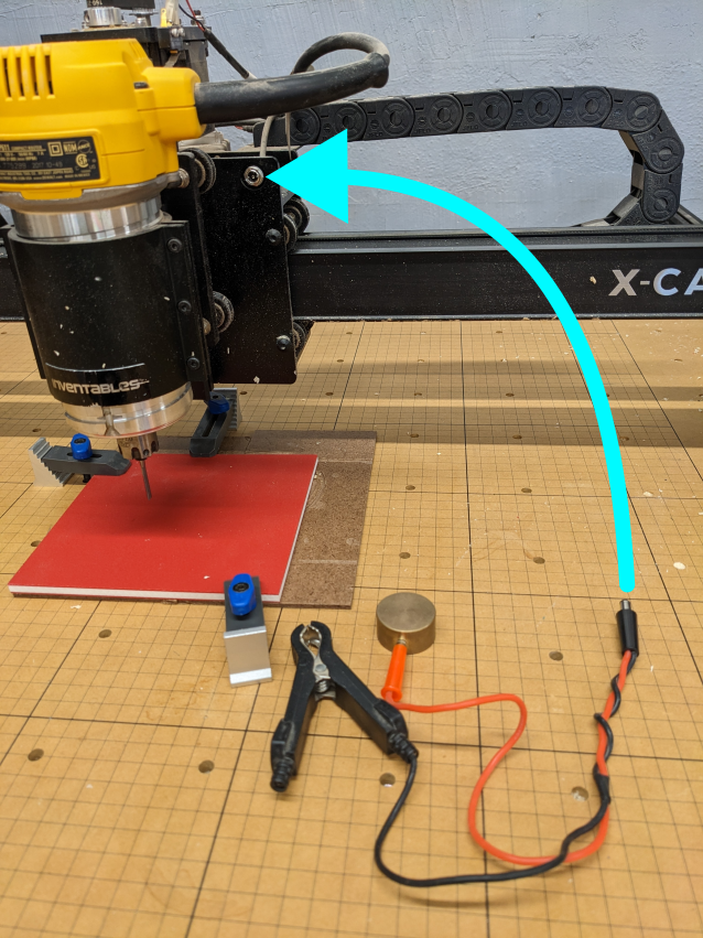
| − | |[[file:| | + | |[[file:WS X-Carve CarveProbePlugInstall.png|400px|center]] |
| | | | ||
| − | Plug | + | * Plug the barrel plug into the silver jack on the X-Carve. |
| + | ** The jack can be found behind the router on the top of Z-axis carriage | ||
| + | * The checkbox after '''Plug the lead into the carriage''' will automatically turn green, and move you to the next step | ||
|- | |- | ||
! scope="row" | Step 4: | ! scope="row" | Step 4: | ||
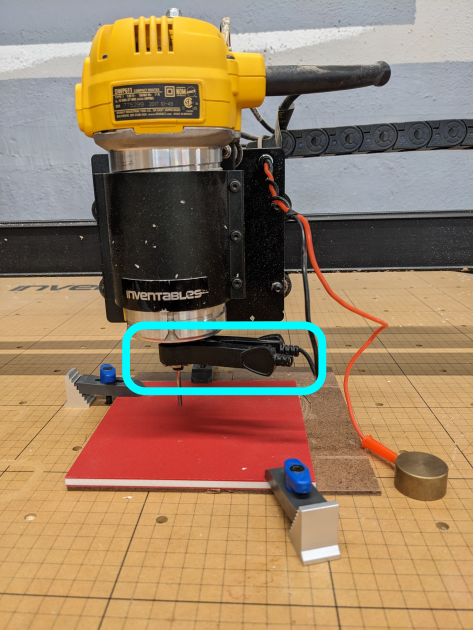
| − | |[[file:| | + | |[[file:WS X-Carve CarveProbeClipInstalledMarkup.png|400px|center]] |
| + | |||
| + | [[file:WS X-Carve CarveWorkZeroAutoClipMarkup.png|400px|border|center]] | ||
| | | | ||
| − | Attach clip to collet | + | * Attach the black spring clip to the collet assembly on the spindle router. |
| + | ** The metal jaws of the clip must make contact with the metal of the collet assembly | ||
| + | * When the black spring clip is installed, click on the blue '''Clip is attached''' button | ||
|- | |- | ||
! scope="row" | Step 5: | ! scope="row" | Step 5: | ||
| − | |[[file:| | + | |[[file:WS X-Carve CarveProbePlateTouchMarkup.png|400px|center]] |
| | | | ||
| − | + | * Gently touch the brass touch plate to the cutting bit. | |
| + | * The ''No contact'' light will turn to '''Contact''' and automatically move you to the next step | ||
|- | |- | ||
! scope="row" | Step 6: | ! scope="row" | Step 6: | ||
| − | |[[file:| | + | |[[file:WS X-Carve CarveProbePlateReadyMarkup.png|400px|center]] |
| + | |||
| + | [[file:WS X-Carve CarveWorkZeroAutoTouchPlateButtonMarkup.png|400px|border|center]] | ||
| | | | ||
| − | Place plate below bit | + | * Place the brass touch plate directly below the cutting bit |
| + | * Click the blue '''Touch place it in place''' button | ||
|- | |- | ||
! scope="row" | Step 7: | ! scope="row" | Step 7: | ||
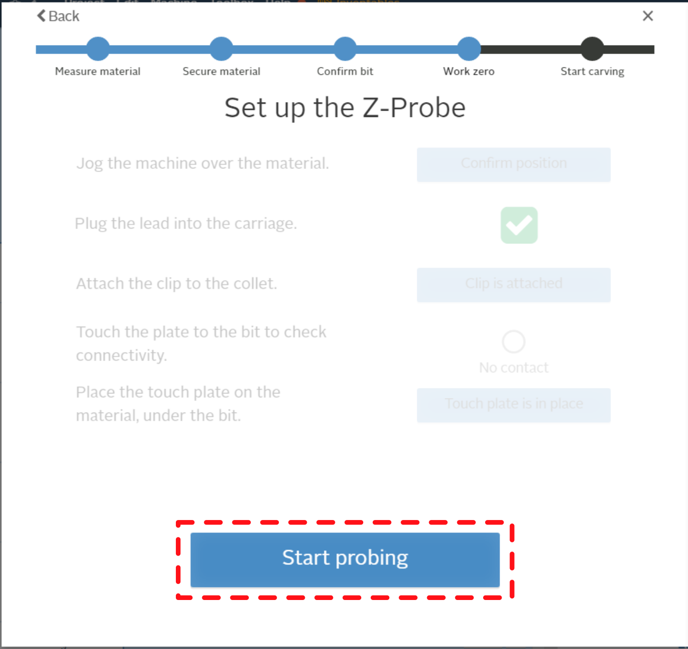
| − | |[[file:| | + | |[[file:WS X-Carve CarveWorkZeroAutoStartProbingMarkup.png|400px|center]] |
| | | | ||
| − | Press | + | * Press the '''Start probing''' button |
|- | |- | ||
! scope="row" | Step 8: | ! scope="row" | Step 8: | ||
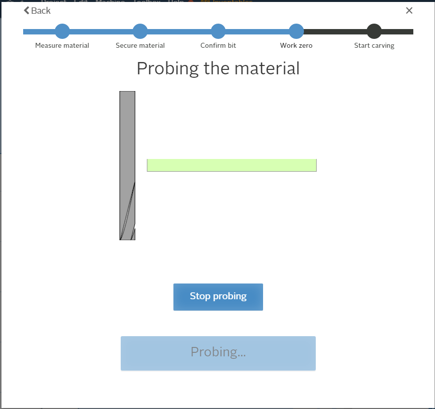
| − | |[[file:| | + | |[[file:WS X-Carve CarveWorkZeroAutoProbing.png|400px|center]] |
| | | | ||
| − | + | * The X-Carve will automatically move the Z-axis down until the tip of the cutting bit contacts the touch plate, then retract. | |
|- | |- | ||
! scope="row" | Step 9: | ! scope="row" | Step 9: | ||
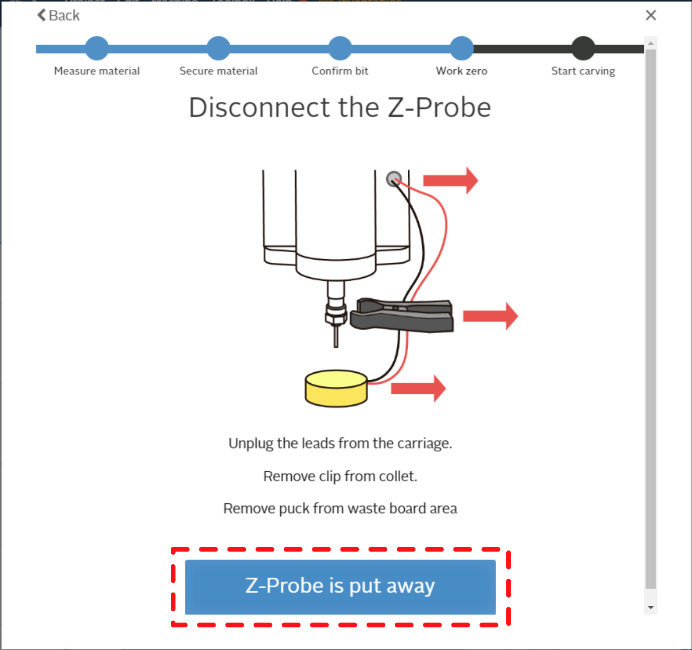
| − | |[[file:| | + | |[[file:WS X-Carve CarveWorkZeroAutoDisconnectMarkup.png|400px|center]] |
| | | | ||
| − | + | * Gently pull the barrel plug from the jack on the X-Carve | |
| + | * Disconnect the black spring clip from the collet assembly | ||
| + | * Put the Z-probe back in the cart tool tray | ||
| + | * Click the blue '''Z-Probe is put away''' | ||
|- | |- | ||
! scope="row" | Step 10: | ! scope="row" | Step 10: | ||
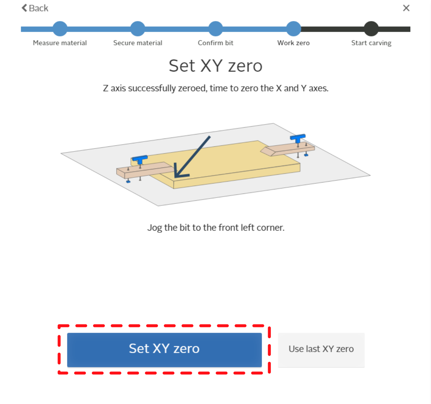
| − | |[[file:| | + | |[[file:WS X-Carve CarveWorkZeroAutoXYCornerMarkup.png|400px|center]] |
| | | | ||
| − | Set | + | * Jog the tip of the cutting bit to above the corner of the workpiece |
| + | ** Avoid crashing the cutting bit into clamps, fixtures, or jigs on the table | ||
| + | ** Job intervals should be reduced as the cutting bit gets closer to the workpiece | ||
| + | ** The tip of the cutting bit can be any height above the workpiece | ||
| + | * When the tip of the cutting bit is just above the lower left corner of the workpiece, click the blue '''Set XY zero''' button. | ||
| + | |||
| + | |||
| + | There is also a ''Use last XY zero'' button. This button may be used when: | ||
| + | * Multiple cutting operations are being performed on the same part with the same cutting bit | ||
| + | * Multiple instances of identical parts are being cut using a fixed alignment jig | ||
|- | |- | ||
|} | |} | ||
| − | === | + | ==== Manual Work Zero ==== |
{| class="wikitable" | {| class="wikitable" | ||
|- | |- | ||
! scope="row" | Step 1: | ! scope="row" | Step 1: | ||
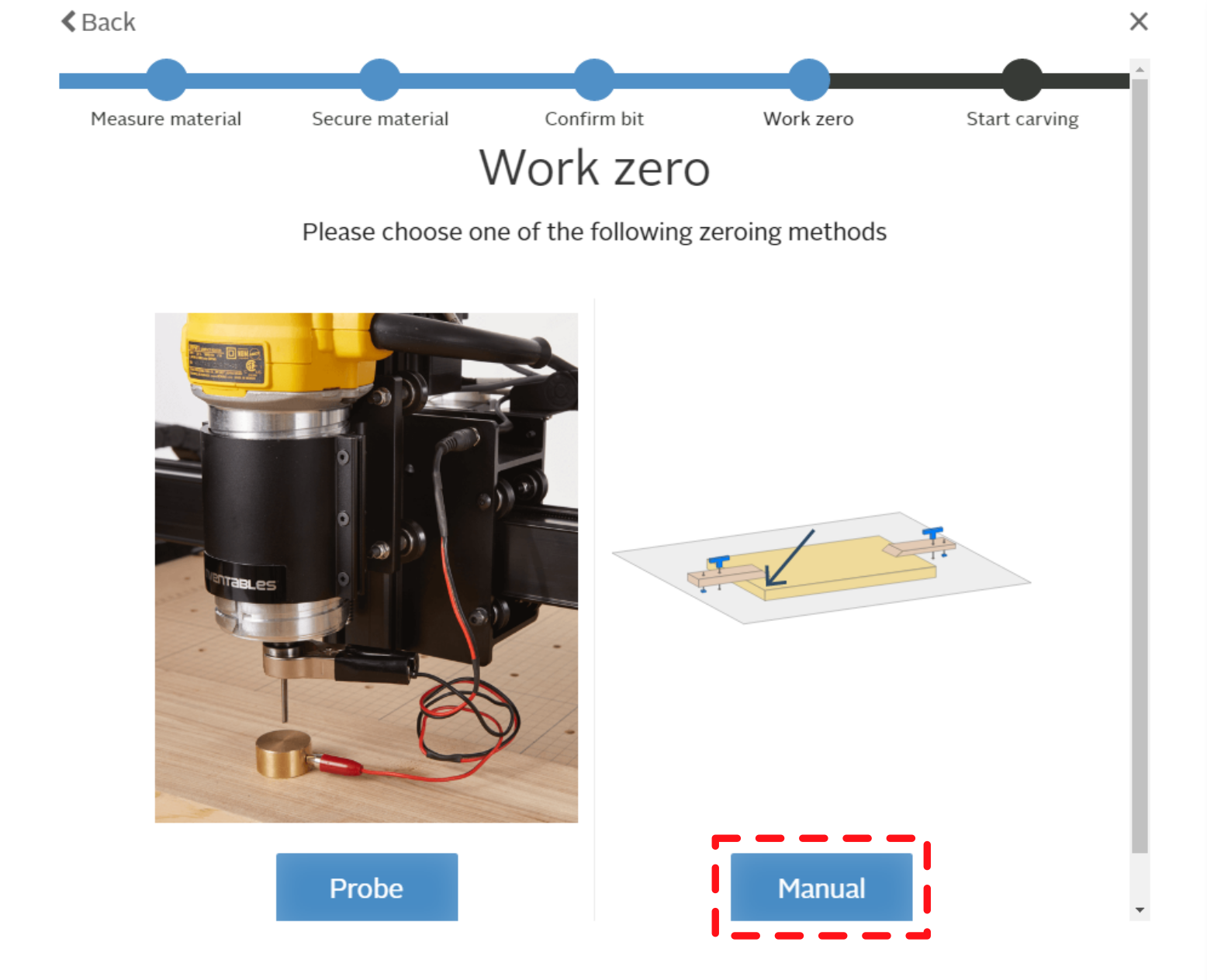
| − | |[[file:|center]] | + | |[[file:WS X-Carve CarveWorkZeroChoiceManualMarkup.png|400px|center]] |
| | | | ||
| − | + | * Click the blue '''Manual''' button | |
|- | |- | ||
! scope="row" | Step 2: | ! scope="row" | Step 2: | ||
| | | | ||
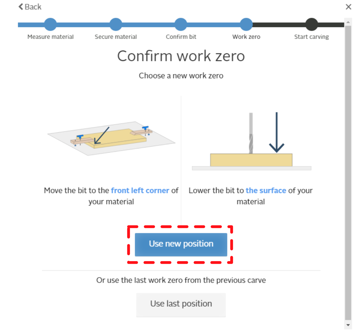
| − | [[File:|center]] | + | [[File:WS X-carve CarveManualWorkZeroMarkup.png|400px|center]] |
| | | | ||
| − | + | * Jog the tip of the cutting bit to just touch the corner of the workpiece | |
| + | ** Avoid crashing the cutting bit into clamps, fixtures, or jigs on the table | ||
| + | ** Care must be taken when making contact to prevent damage to the cutting bit or workpiece | ||
| + | ** Job intervals should be reduced as the cutting bit gets closer to the workpiece | ||
| + | * When the tip of the cutting bit is just touching the lower left corner of the workpiece, click the blue '''Use new position''' button. | ||
| + | |||
| + | |||
| + | There is also a ''Use last position'' button. This button may be used when: | ||
| + | * Multiple cutting operations are being performed on the same part with the same cutting bit | ||
| + | * Multiple instances of identical parts are being cut using a fixed alignment jig | ||
|- | |- | ||
|} | |} | ||
Revision as of 01:32, 29 May 2023
This tutorial is Part 3 of the X-Carve Router practice example. This portion of the example will explain how to set up the coordinates for your carve, and carve your example part. If you haven't yet, go complete Part 1 and Part 2 first.
| Login to Easel and Start a New Project |
| Part 1: Creating Geometry and Features |
| Part 2: Setting Up the Machine |
| Part 3: Carving the Part |
Connecting the Computer to the Controller
Only the computer in the Woodshop should be used to run X-Carve programs. It is freely accessible for any members with Woodshop Access.
| Step 1: |
Log into the computer using following credentials:
| |
|---|---|---|
| Step 2: |
| |
| Step 3: |
|
Homing and Jogging The Machine
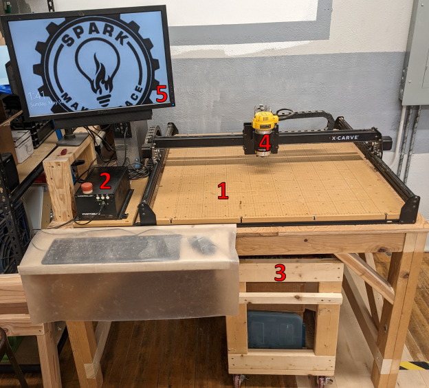
You're almost ready to cut your project on the X-Carve. Before you get to carving, there's a few things you'll need to know about controlling the X-Carve spindle position using the computer.
KEEP HANDS AND FINGERS CLEAR OF THE X-CARVE WHEN IT IS OPERATING
| Step 1: |
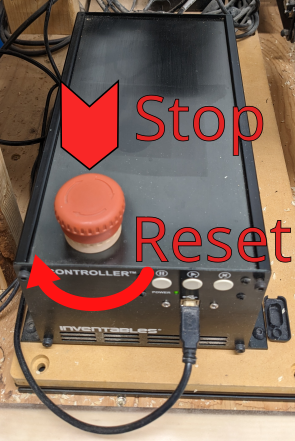
There are two buttons in the upper right corner of the Easel window. Depending on the state of the X-Carve controller, they may be blue or green. If the buttons are blue, the X-Carve controller is not connected to the computer.
| |
|---|---|---|
| Step 2: |
Once the buttons have turned green, the X-Carve controller is correctly connected to the computer. The Carve... button will be used later. Right now, click the button with four arrows to open the Jog controls. | |
| Step 3: |
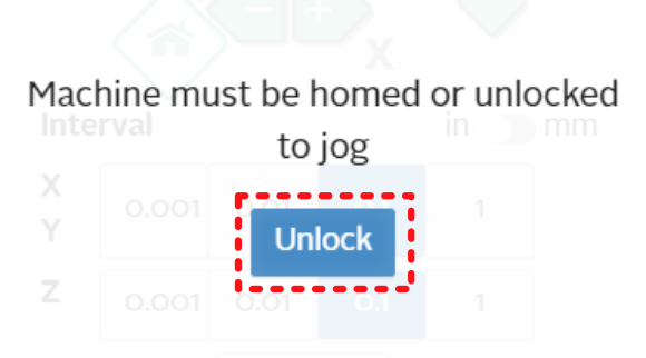
Easel will ask you to unlock the machine prior to allowing access to the jog controls. Be aware that the machine can start moving by itself from this point forward. Keep hands, fingers, etc. clear of the machine table. Click the Unlock button to access the jog control panel. | |
| Step 4: |
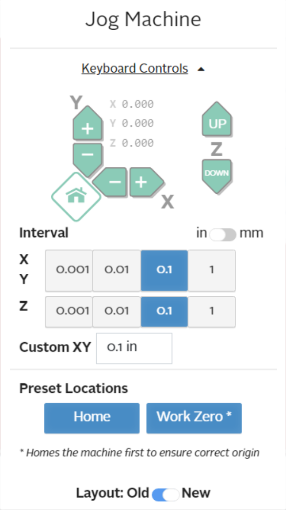
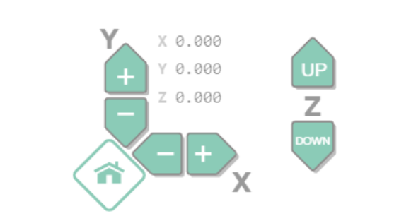
Jogging is a method of moving the spindle manually, by directly controlling the machine motors. Jogging the machine does not respect the limit switches. The machine will follow user directions, even when it will damage the machine. Users must use the jog commands carefully and responsibly to prevent breaking the X-Carve. The Jog Machine panel has several sections, which are described in additional detail below. Two general controls should be mentioned first, however.
| |
| Step 5: |
The first part of the jog panel shows the buttons for direction controls. Each set of arrow buttons control a single axis.
Also shown is a set of coordinates on all three axes. In this image at left, the machine is in the Home position, and all three coordinate values are zero. Clicking the arrow buttons for each axis will move the spindle in the associated direction. Care should be taken when near the edges of the table to prevent exceeding the limits of machine travel. | |
| Step 6: |
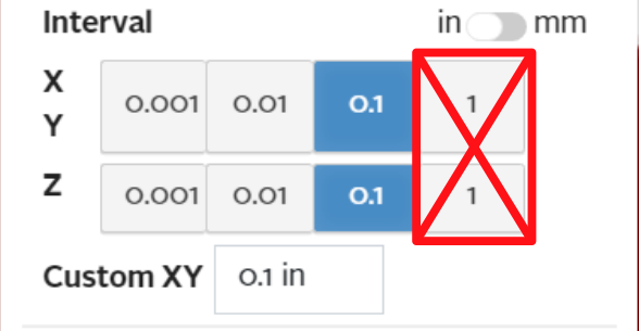
The next part of the jog panel shows the options for travel rate, or interval. The interval is the distance traveled by the spindle for each click on one of the directional controls. The standard settings are factors of 10 in inches, but the interval can be set in to millimeters, or set for custom interval values. Due to control issues, users are advised to use only the lower three settings. The travel rate, particularly in the Z-axis, using the highest setting is dangerous for the machine. | |
| Step 7: |
The last portion of the jog panel has two buttons on it.
|
Carving!
Finally, it's time to actually make chips. There are three portions of this step: preparing the cut, setting up the work zero, and cutting the part.
Preparing
| Step 1: |
Press the Carve... button in the upper right corner of the Easel window. | |
|---|---|---|
| Step 2: |
| |
| Step 3: |
| |
| Step 4: |
|
Setting Work Zero
Defining the work zero means telling the X-Carve where the tip of the cutting bit is, and where the workpiece is. There are two was to do with: with the Z-axis probe, and by manually touching the tip of the cutting bit to the corner of the workpiece. Using the probe is usually faster and more accurate. It is also less likely to break or damage very small cutting bits. For this example, Spark recommends using the probe, but both methods are described below.
The Z-probe is three pieces, connected by wires. There is a barrel plug, with one black wire and one red wire coming out. The black wire connects to a spring clip. The red wire connects to a brass touch plate. The Z-probe should be stored in the cart tool tray when not in use.
Probe Work Zero
| Step 1: |
| |
|---|---|---|
| Step 2: |
| |
| Step 3: |
| |
| Step 4: |
| |
| Step 5: |
| |
| Step 6: |
| |
| Step 7: |
| |
| Step 8: |
| |
| Step 9: |
| |
| Step 10: |
|
Manual Work Zero
| Step 1: |
| |
|---|---|---|
| Step 2: |
|
Carve Start and Operation
| Step 1: | [[file:|center]] |
Check the router speed Power router on |
|---|---|---|
| Step 2: |
[[File:|center]] |
Confirm spindle is running |
| Step 3: |
[[File:|center]] |
Press Carve button |
| Step 4: |
[[File:|center]] |
Mid-carve controls |
| Step 5: |
[[File:|center]] |
Done! |
| Step 6: |
[[File:|center]] |
Clean up |
