This tutorial is Part 2 of the X-Carve Router practice example. This portion of the example will explain parts of the X-Carve table at Spark, and how to mount the material to the machine table, install the cutting tool, and set the router speed. If you haven't yet, go complete Step 1 first.
Approaching the X-Carve
The X-Carve machine is near the main entry door into the Spark Woodshop. As you approach the machine, you'll see the following parts:
|
|
- The X-Carve table, with a 1cm X 1cm grid and threaded holes for clamping.
- The X-Carve controller, with a big red button on it called the emergency stop, or E-stop.
- A cart under the machine, which has important accessories required to use the machine (explained further below)
- The X-Carve spindle is a DeWalt router. It is controlled manually, meaning the user has to turn the spindle on and off before carving.
- The X-Carve is controlled by the attached computer.
|
|
|
The important part of the controller is the emergence stop, usually shorthanded to E-stop. It is the large red button on the controller, and is actuated by pressing straight down on it. This will immediately stop the motion of the machine, but will not stop the router spindle. The router spindle is controlled manually, and must be shut off separately.
Don't be afraid to use the E-stop if the machine is doing anything unexpected.
To reset the E-stop after correcting the problem, twist the red portion of the button clockwise. It will spring up and the X-Carve will be ready to run again.
|
|
|
Pulling out the cart under the machine gives access to the tool tray. The tools should be returned to the tray whenever they are not in use.
The image at left shows the various types of tools, divided by color:
- RED: The two red boxes show the parts used for clamping material to the table bed. The upper box surrounds the clamping screws. The lower box surrounds the plastic clamp arms and the aluminum clamp bases.
- BLUE: The two blue boxes show shop cutting bits. Some may be in the plastic protective sleeve, which fits in the square pockets on the left. Others may be out of the sleeve, and stored in the holes in the middle of the image.
- YELLOW: The two objects in the yellow box are the collet assemblies. Each assembly contains a collet and a collet nut. One set is for 1/8-inch shank cutters, and the other is for 1/4-inch shank cutters.
- PURPLE: There are two wrenches, for use with the collet assemblies, circled in purple. The wrench with the red handle is for the 1/8-inch collet assembly; the larger end of the silver wrench is for the 1/4-inch collet assembly.
- GREEN: The green box identifies the Z-probe, which is used to set the tool length.
- There are also usually brushes in the tray, as shown in the image at left.
- Please ensure the tray is completely under the table when cutting, to prevent sawdust accumulation.
|
Mount Material to Table
Prior to using the X-Carve the workpiece must be firmly mounted to the the machine table. This requires use of the clamping parts found in the top tray of the cart.
It is also important to ensure that a spoil board is used whenever cuts are made through the workpiece. A spoil board is a sacrificial panel which protects the bed to the machine from being cut into. Several instances of careless cutting are visible on the Spark X-Carve bed. Please help prevent any more damage!.
PRIOR TO WORKING ON THE X-CARVE TABLE, ENSURE THE E-STOP BUTTON IS PRESSED DOWN
| Step 1:
|
|
As shown to the left, the workpiece is red with a white core. Two pieces of brown tempered hardboard* are being used as spoil boards.
At least two, ideally three or four, clamps should be used. One clamp is composed of three parts:
- A plastic clamp arm. These are available in several lengths in the cart tray. One end is tapered, and the other end has a step pattern to engage the clamp base.
- An aluminum clamp base. The profile of this part looks like a toothy triangle. The teeth lock into the stepped end of the clamp arm.
- A clamp screw. Again, these are available in several lengths in the cart tray, with each length having color matching heads.
- The screws should be long enough to engage the threads in the X-Carve bed, but short enough that they can be tightened against the clamp arm without bottoming out in the X-carve bed.
*also commonly called by the trade name Masonite
|
| Step 2:
|
|
Clamps should be assembled by:
- Aligning the clamp arm slot with a threaded hole in the machine table
- Checking that the tapered end of the clamp arm will reach the workpiece
- Checking that the stepped end of the clamp arm will have clearance to engage into the clamp base
- The clamp arm should slope up slightly from the workpiece to the clamp base, as shown to the left
- If the clamp base is not tall enough, use a taller base or one of the base extension blocks
- Insert a clamp screw through the slot in the clamp arm, and into the threaded hole in the machine table
- The clamp screw should be long enough to have three or more complete turns of thread engagement before contacting the clamp arm. Less thread engagement may not have enough clamping force to hold down the part, and can damage the clamping threads on both the clamp screw and the machine table.
- Gently tighten the clamp screw. It should be firmly holding the workpiece down, but remember the clamp arms are only plastic.
|
| Step 2A:
|
|
- Avoid clamping setup which slope down from the workpiece
- Avoid overtightening the clamp screws
|
| Step 3:
|
|
- At least two clamps are required to hold a workpiece in position. More are recommended whenever possible.
- Care should be taken in clamp placement, particularly to avoid the paths of the cutter during machining.
- The lower left corner of the workpiece is the usual "home" position of the cutter and workpiece. Avoid placing clamps in the lower left corner of the workpiece.
Note that in this case, three clamps have been used. Both the part and the spoil board have been aligned with the grid on the machine table.
|
| Step 3A:
|
|
Careless clamp placement can result in damage to the clamp arms, as shown to the left. The left clamp arm is in good shape; the other two have suffered from careless clamp placement.
|
Install the Cutting Bit
The other major part of the machine setup is installing the cutting bit. The bit should match the bit definition in Easel.
PRIOR TO WORKING ON THE X-CARVE TABLE, ENSURE THE E-STOP BUTTON IS PRESSED DOWN
| Step 1:
|
|
The first step is to choose the correct collet assembly for your cutter.
- Each collet assembly contains a collet and a collet nut; they should always stay together.
- If you think you have a reason to take the collet nut off the collet, first talk to the Woodshop Leads.
- The Spark X-Carve has 1/8-inch and 1/4-inch collet assemblies.
- The 1/8-inch collet assembly requires a special pronged wrench
- The 1/4-inch collet assembly takes a standard 17mm box wrench
The collet assembly size should match the diameter of the cutting tool shank
|
| Step 2:
|
|
To install the cutting bit in the collet:
- Insert the shank of the bit into the collet
- The collet should ride on the smooth, round portion of the cutting tool
- The protrusion of the tool should be kept as short as possible
- Thread the collet assembly onto the bottom of the spindle router
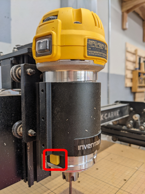
- The spindle lock is a yellow button on the bottom left of the spindle
- It may be necessary to hold the spindle lock while threading the collet assembly onto the spindle threads
|
| Step 3:
|
|
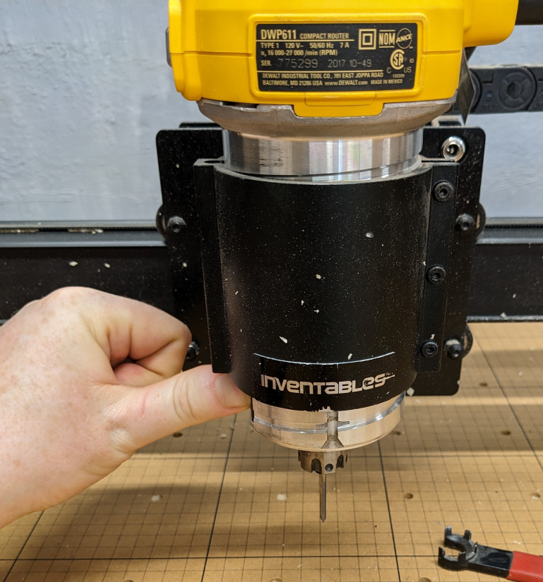
To finish the installation:
- Ensure the cutting tool is fully inserted into the collet assembly
- Ensure the collet is gripping the smooth, round portion of the cutting tool
- Using the appropriate wrench, tighten the collet nut
- Return the wrench to the cart tool tray
|
Final Checklist
Done with the install? Check the items below before moving on.
- The clamp arms are angled correctly
- The clamp screws are tightened
- The part is firmly held to the table - no wiggles, wobbles, or floppy corners
- The cutting bit is firmly held in the spindle collet
- Any spare clamp parts or assembly tools are back in the cart tool tray
Now you're ready to go to Part 3: Carving.


