Difference between revisions of "X-Carve: Example Machine Setup"
| Line 44: | Line 44: | ||
==Mount Material to Table== | ==Mount Material to Table== | ||
| − | + | Prior to using the X-Carve the workpiece must be firmly mounted to the the machine table. This requires use of the clamping parts found in the top tray of the cart. | |
It is also important to ensure that a spoil board is used whenever cuts are made through the workpiece. A spoil board is a sacrificial panel which protects the bed to the machine from being cut into. Several instances of careless cutting are visible on the Spark X-Carve bed. Please help prevent any more damage! | It is also important to ensure that a spoil board is used whenever cuts are made through the workpiece. A spoil board is a sacrificial panel which protects the bed to the machine from being cut into. Several instances of careless cutting are visible on the Spark X-Carve bed. Please help prevent any more damage! | ||
| Line 80: | Line 80: | ||
| | | | ||
AVOID CRASHING CLAMPS | AVOID CRASHING CLAMPS | ||
| + | |- | ||
| + | |} | ||
| + | |||
| + | |||
| + | |||
| + | ==Install the Cutting Bit== | ||
| + | |||
| + | The first step in setting up the X-Carve is to mount the material on the machine table. This requires use of the clamping parts found in the top tray of the cart. | ||
| + | |||
| + | It is also important to ensure that a spoil board is used whenever cuts are made through the workpiece. A spoil board is a sacrificial panel which protects the bed to the machine from being cut into. Several instances of careless cutting are visible on the Spark X-Carve bed. Please help prevent any more damage! | ||
| + | |||
| + | {| class="wikitable" | ||
| + | |- | ||
| + | ! scope="row" | Step 1: | ||
| + | |[[file:|x400px|center]] | ||
| + | | | ||
| + | STEP 1 GOES HERE | ||
| + | |- | ||
| + | ! scope="row" | Step 2: | ||
| + | | [[file:|x300px|center]] | ||
| + | | | ||
| + | STEP 2 GOES HERE | ||
| + | |- | ||
| + | ! scope="row" | Step 3: | ||
| + | |[[file:|x300px|center]] | ||
| + | | | ||
| + | STEP 3 GOES HERE | ||
| + | |- | ||
| + | ! scope="row" | Step 4: | ||
| + | |[[file:|x300px|center]] | ||
| + | | | ||
| + | STEP GOES HERE | ||
| + | |- | ||
| + | ! scope="row" | Step 5: | ||
| + | |[[file:|x300px|center]] | ||
| + | | | ||
| + | STEP 5 GOES HERE | ||
|- | |- | ||
|} | |} | ||
Revision as of 19:05, 21 May 2023
This tutorial is Step 2 of the X-Carve Router practice example. This portion of the example will explain parts of the X-Carve table at Spark, and how to mount the material to the machine table, install the cutting tool, and set the router speed. If you haven't yet, go complete Step 1 first.
Approaching the X-Carve
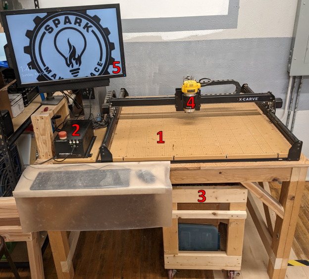
The X-Carve machine is near the main entry door into the Spark Woodshop. As you approach the machine, you'll see the following parts:
| |
|
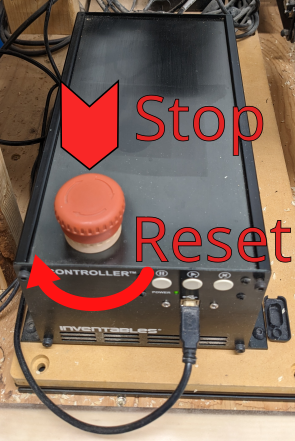
The important part of the controller is the emergence stop, usually shorthanded to E-stop. It is the large red button on the controller, and is actuated by pressing straight down on it. This will immediately stop the motion of the machine, but will not stop the router spindle. The router spindle is controlled manually, and must be shut off separately. Don't be afraid to use the E-stop if the machine is doing anything unexpected. To reset the E-stop after correcting the problem, twist the red portion of the button clockwise. It will spring up and the X-Carve will be ready to run again. | |
|
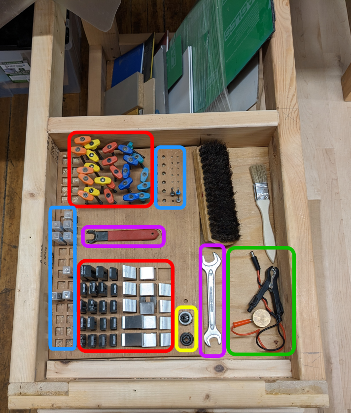
Pulling out the cart under the machine gives access to the tool tray. The tools should be returned to the tray whenever they are not in use. The image at left shows the various types of tools, divided by color:
|
Mount Material to Table
Prior to using the X-Carve the workpiece must be firmly mounted to the the machine table. This requires use of the clamping parts found in the top tray of the cart.
It is also important to ensure that a spoil board is used whenever cuts are made through the workpiece. A spoil board is a sacrificial panel which protects the bed to the machine from being cut into. Several instances of careless cutting are visible on the Spark X-Carve bed. Please help prevent any more damage!
| Step 1: |
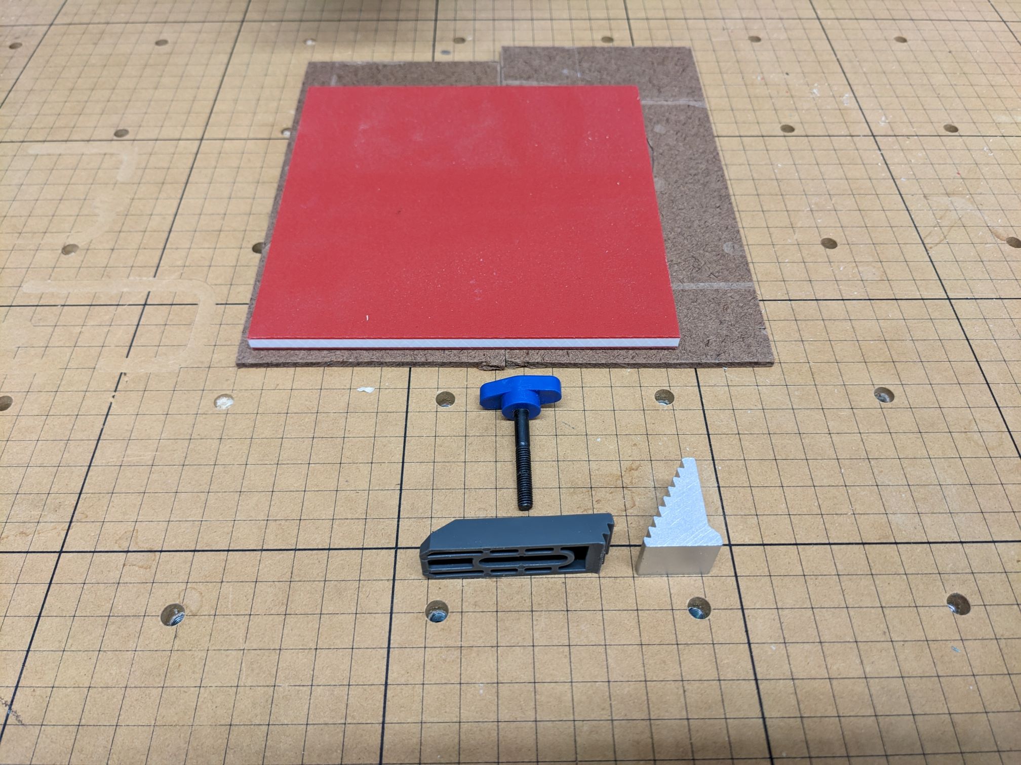
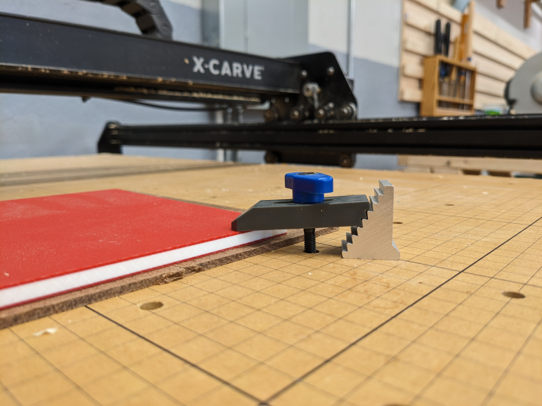
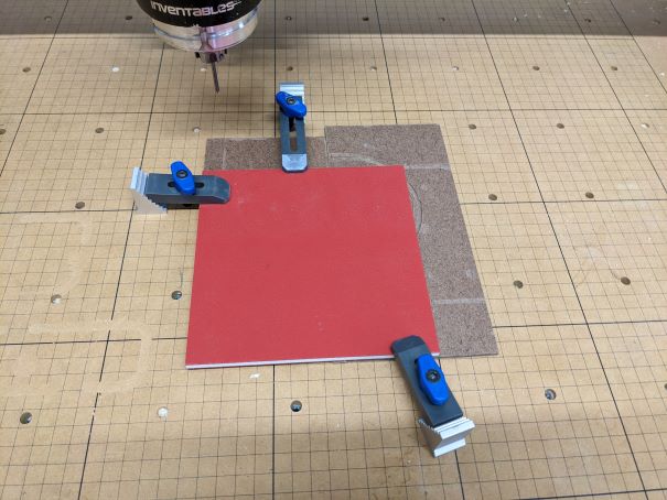
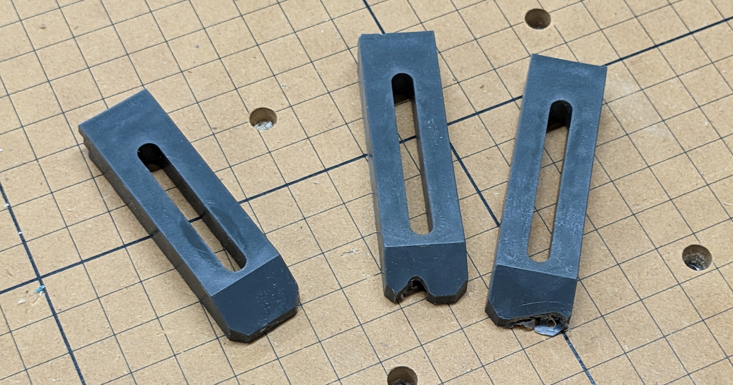
As shown to the left, the workpiece is red with a white core. Two pieces of brown tempered hardboard (also commonly called by the trade name Masonite) are being used as spoil boards. At least two, ideally three or four, clamps should be used. One clamp is composed of three parts:
| |
|---|---|---|
| Step 2: |
CLAMP ASSEMBLY GOES HERE | |
| Step 2A: |
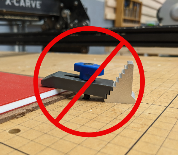
GOOD/BAD Examples go here | |
| Step 3: |
INSTALL OTHER CLAMPS | |
| Step 3A: |
AVOID CRASHING CLAMPS |
Install the Cutting Bit
The first step in setting up the X-Carve is to mount the material on the machine table. This requires use of the clamping parts found in the top tray of the cart.
It is also important to ensure that a spoil board is used whenever cuts are made through the workpiece. A spoil board is a sacrificial panel which protects the bed to the machine from being cut into. Several instances of careless cutting are visible on the Spark X-Carve bed. Please help prevent any more damage!
| Step 1: | [[file:|x400px|center]] |
STEP 1 GOES HERE |
|---|---|---|
| Step 2: | [[file:|x300px|center]] |
STEP 2 GOES HERE |
| Step 3: | [[file:|x300px|center]] |
STEP 3 GOES HERE |
| Step 4: | [[file:|x300px|center]] |
STEP GOES HERE |
| Step 5: | [[file:|x300px|center]] |
STEP 5 GOES HERE |
